Specialized in manufacturing compensators, expansion joints, baffle doors
A comprehensive scientific and technological enterprise integrating design and development, production, product sales, installation and debugging
Specialized in the production of metal compensator, non-metal compensator, baffle door equipment for 18 years
Product Center
Specialized in manufacturing a variety of high-quality industrial equipment to meet your diverse needs
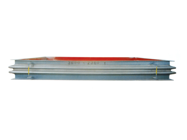
Metal rectangular expansion joint
Product introduction of metal rectangular expansion jointProduct Structure and C...
Learn more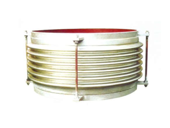
Universal corrugated expansion joint
The universal corrugated expansion joint is a kind of flexible compensation elem...
Learn more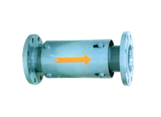
Single axial expansion joint
I. Structural compositionThe single axial expansion joint is mainly composed of ...
Learn moreCompensator, baffle door equipment · One-stop service process
From consultation to installation, we offer a full range of professional services
Consultation needs
The professional team will provide you with detailed product consultation and technical support to understand your specific needs
Scheme design
Provide personalized product design according to your specific needs to ensure the best solution
Manufacturing
Adopt advanced production equipment and technology and strict quality control to ensure excellent product quality
Installation and commissioning
Professional technicians provide on-site installation and commissioning services to ensure the normal operation of the equipment
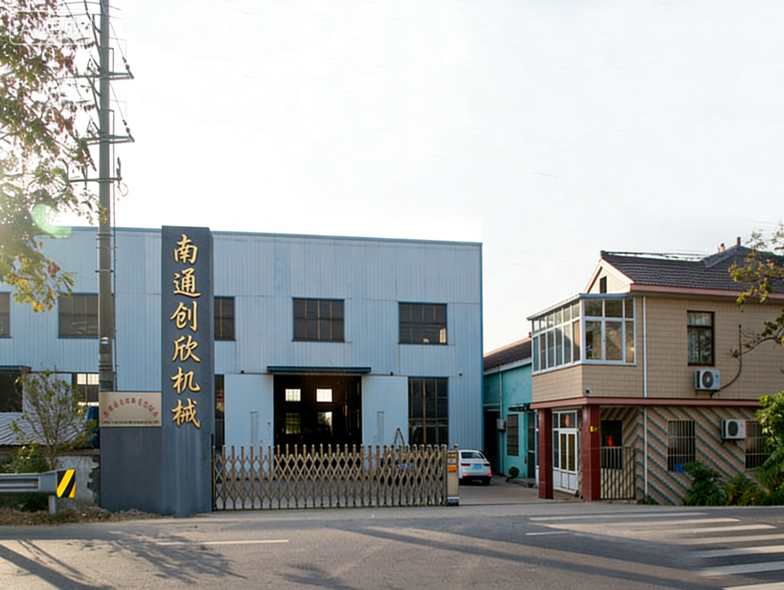
About Us
Nantong Chuangxin Machinery Co., Ltd. is located in the plain of central Suzhou, close to Nantong and Ningjingyan Expressway with convenient transportation, and less than 2 hours drive from Shanghai, Suzhou, Wuxi, Nanjing and other large and medium-sized cities.
The company is a comprehensive scientific and technological enterprise integrating design and development, production, product sales, installation and debugging. The company has successively communicated and cooperated with the National Cement Research Institute and the general contractor!
The company's main products are metal compensator (expansion joint), non-metal compensator (expansion joint), baffle door and other series products, providing excellent and cheap complete sets of equipment for the majority of users at home and abroad.
NEWS
Stay up-to-date with company and industry updates
How to choose a new metal expansion joint? Find out these points before you start
Don't ask the model in a hurry. Tell me what your working condition is...
Before choosing 304 metal corrugated expansion joint, find out these four things first
Before choosing 304 metal corrugated expansion joint, find out these f...
80% of the pits of the metal expansion joint of the returner are in the type selection stage
Two days ago, I received a phone call from a customer, saying that the...
How to choose metal expansion joint to be efficient? Explain from structure to working condition at one time
Find out what "efficient" means firstTwo days ago, I met a customer an...
How to choose the material of metal expansion joint? Doorways from bellows to takeovers
Corrugated pipe material is the core, so why does stainless steel domi...
The appearance of the metal expansion joint, the layman looks at the ripples, the insider looks at the doorway
The density and depth of ripples is not a question of whether they loo...
Frequently asked questions
Answers to your frequently asked questions about compensators and baffle doors
It is also a corrugated expansion joint. Why is the height difference of the wave sidewall so much? Find out exactly where this parameter refers first
What is the sidewall height of expansion joint wave? To be honest, there is a problem with this question itself-the height of the wave sidewall is not a fixed value, it follows the working conditions. Don't rush to ask "how much" first, find out which paragraph it refers to.
The waveform of the corrugated expansion joint, you can understand it as a wave. The hypotenuse between the peak and the trough, that is, the vertical distance from the bottom of the trough to the top of the peak, is called wave height in the industry, but when the engineering drawings are actually processed and inspected, it is actually the "wave sidewall height"-it refers to the vertical projection size of the inclined wall on the side of the bellows. Many people confuse it with wave height, which is not exactly the same thing. When you measure with a caliper, you measure the height from the trough to the peak, but the height of the wave sidewall should also consider the transition radius between the peak arc and the trough arc. The measured value will be slightly different from the wave height.
This size directly determines the stiffness, pressure resistance and compensation amount of the expansion joint. The same nominal diameter, high wave side wall height, good flexibility, large compensation, but the pressure resistance will decrease; On the other hand, if the wave side wall height is low, the pressure bearing capacity is strong, but the compensation capacity is limited. So do you say that this parameter is heavy or not? When you can't figure out the selection, most of the problems will occur when you install the pressure test later.
Is there a fixed standard for wave sidewall height? From GB/T 12777 to the actual product, see how it is determined
Some people think that the national standard will specify an exact wave sidewall height for each path, which is overthinking. GB/T 12777 General Technical Conditions for Expansion Joints of Metal Corrugated Pipe mainly stipulates the design, manufacture, inspection and acceptance requirements of corrugated pipe, and gives framework things such as design calculation method, material selection principle and fatigue life test method, which will not determine the height of wave sidewall alone.
There is a parameter table of bellows section dimensions in the standard, which lists the recommended values such as wave height, wave pitch, wave number and wall thickness, but these are design references, not mandatory standards. The same corrugated expansion joint of DN200 is used in low-pressure and large-compensation applications and high-pressure and small-compensation applications, and the wave side wall height is likely to be more than double. For this reason, you can't find a "standard answer" in the national standard. What about that? It has to be pushed from the design source.
There are four key factors affecting the height of wave sidewall: pressure, caliber, material and compensation amount
Let's talk about how the height of the wave sidewall was "forced" out in actual design. Four factors are indispensable:
Stress.This is the first deciding factor. The higher the internal pressure, the greater the circumferential stress on the bellows wall. If the height of the sidewall of the wave is too high, the stress is easy to concentrate at the trough, and the pressure resistance is immediately discounted. Therefore, under high-pressure working conditions, the height of the wave side wall is usually pressed relatively low, the wave shape is flat, and multi-layer thin walls are used to make up the flexibility. On the other hand, in the working conditions of low pressure and large displacement, such as non-metallic expansion joints or large-diameter metallic expansion joints for smoke ducts, the height of wave sidewall can be made higher, and the waveform can be stretched, so that the compensation amount can go up.
Caliber.The larger the diameter, the larger the pressure bearing area, and the greater the total thrust under the same pressure. The design requirements of the expansion joints of DN100 and DN2000 are completely different from the same order of magnitude. Large diameter expansion joint should control the ratio of wave side wall height to avoid excessive plastic deformation of wave trough. For example, the rectangular expansion joint on the smoke duct of power station, which has a super large diameter, is often iterated by finite element analysis, instead of copying the empirical value of small diameter.
Materials.The yield strength and fatigue characteristics of austenitic stainless steels (e.g. 304, 316L) determine how much bending strain the bellows can withstand. The material strength is high, which can make the height of the wave sidewall larger, and the wave shape can hold it anyway; If the material is low in strength or thin in thickness, the situation is the other way around. There is also the problem of material creep under high temperature working conditions. As soon as the temperature rises, the allowable stress of the material drops, and the height of the wave side wall has to be lowered accordingly, otherwise the bellows is easy to become unstable under high temperature.
The amount of compensation.The larger the displacement to be absorbed, the larger the deformation of each wave, and the height of the wave sidewall should naturally be made higher. However, the fatigue life of bellows is directly linked to the displacement of single wave, and it is not because you can increase the compensation infinitely by pulling the height of the wave sidewall hard. Axial type, transverse type and hinge type, each type has different requirements for the height of wave sidewall. Under the working condition of transverse displacement, the height of wave sidewall has a great influence on the shear deformation of corrugated pipe, so it should be specially checked during design.
The height of the wave side wall is not determined by patting the head: what data are mainly looked at in design calculation?
Then how exactly do the designers set this size? The core path is as follows: first, according to the pipeline stress analysis, the displacement to be absorbed-axial displacement, lateral displacement and angular displacement is obtained, and then the materials and layers are selected in combination with the design pressure, design temperature and medium corrosion margin, and then the geometric parameters of the bellows are iteratively calculated by the calculation method recommended by EJMA standard or GB/T 12777. The wave sidewall height is not calculated separately, it is a related dimension that follows the wave height, wave distance and wave number.
One is the compressive strength check, to ensure that the bellows will not yield or instability under the most severe working conditions; The other is the fatigue life check, to ensure that penetrating cracks will not occur within the expected number of cycles. If you find that the sidewall height of the expansion knuckle wave reported by the two manufacturers is much different under the same working conditions, don't rush to compare the price. Let them take out the design calculation book first. If the wave sidewall height deviates too far from the conventional value, either the stiffness and fatigue life are not up to standard, or there is another mystery in the material or wall thickness.
How to confirm the wave sidewall height with the manufacturer when selecting the model? What to pay attention to in field measurement and drawing verification
If your project has entered the procurement stage, when confirming the height of the corrugated sidewall with the manufacturer, the safest way is to ask the other party to mark the expansion drawing of the corrugated pipe on the drawing, instead of simply quoting a number. The wave height, wave distance, wave side wall height, number of layers and wall thickness of a single layer should be marked on the drawing. These data are meaningful when put together. If you ask the height of a wave sidewall separately, and the manufacturer gives a number, you can't see whether it is reasonable or unreasonable.
For on-site measurement, just use a vernier caliper or depth gauge to directly measure the distance from the trough to the peak of the bellows. But one thing to remind: Many bellows have protective sleeves or insulation layers on the surface, so you have to remove the outer sheath and measure it again. The measured value is allowed to deviate from the value marked on the drawing. GB/T 12777 has requirements for the dimensional tolerance of corrugated pipe. Generally, the tolerance of wave height is about ±3%, and the wall thickness tolerance is according to the material standard. If the measured deviation exceeds 5%, we should be alert to manufacturing quality problems.
In addition, attention should be paid to distinguish whether it is a single layer or a multilayer structure during measurement. The wave sidewall height of multi-layer bellows is the total height. What you measure from the outside is the outermost contour, but there may be gaps or misalignments between each layer. This should be confirmed with the manufacturer. Two years ago, there was a customer, and the height of the wave sidewall measured by a caliper was 3mm smaller than the drawing. It was not said that the manufacturer cut corners. As a result, it was found that the outer protective ring blocked part of the measurement position. This kind of low-level misunderstanding, it is good to talk about it, but I am afraid that it will not talk about it.
At the end of the day, what is the expansion knuckle wave sidewall height? This question should not be answered by a "standard answer", but by your working condition data. Report the parameters of pressure, temperature, medium, displacement and number of cycles to the manufacturer, and ask them to take out the design calculation book. You will naturally know what range the reasonable wave sidewall height should fall in.
How to judge that non-metallic compensator should be replaced
How to replace a non-metallic compensator? In fact, before asking this question, one thing has to be clear-whether it should be replaced or not. Blind replacement not only wastes money, but also may dismantle the originally stable system.
Non-metallic compensators (often called fabric fiber expansion joints) work in high-temperature flue gas and corrosive media for a long time, and the loop belt is a loss part. When you inspect, focus on these places:crack。 If the surface of silicone rubber coating or fluororubber is cracked and the depth exceeds half of the thickness of the coating, it will basically reach its life;Aging。 Press the surface of the loop band with your hand, and the rebound is slow, hard and brittle, indicating that the material has lost its elasticity;deformation。 Use a ruler to lean on the flange surface. If the ring belt is wrinkled and the local bulge exceeds 10mm, it must be treated;leak。 This is the most direct-there is smoke running out during operation, or obvious wear and penetrating damage can be seen after shutdown. Don't hesitate to arrange replacement directly.
If the internal guide tube of the compensator falls off, or the external stainless steel wire mesh is damaged, resulting in the exposure of the fiber layer, even if the surface looks okay, it is recommended to replace it as soon as possible. This kind of damage will accelerate the overall failure of the ring belt, which won't last long.
Preparation before replacement: Don't rush to do it
How to change a non-metallic compensator? The premise is that security measures are in place. This thing is mostly used in places with harsh working conditions such as smoke duct, desulfurization system and cement kiln tail of power plants. The medium is either high temperature or corrosive gas. In the flue above 200℃, do you dismantle it directly? That's not work, it's life-threatening.
The first step is to stop the machine and relieve pressure. Reduce system pressure to zero and temperature to ambient temperature. Don't save this step-some pipes have dead ends, and the dust accumulation inside is still slowly storing heat. I have seen more than once that the surface can't be seen but the internal temperature is still very high. In the second step, use blind plates or baffle doors to separate the pipes on both sides. Speaking of this, the circular baffle door (double seal) in our station is designed for this kind of maintenance scenario. After locking, it can ensure zero leakage, and the later operation is safe. The third step, padlock, hanging tag and gas detection, is completed according to the factory's LOTO process.
Check spare parts at the same time. The specifications and parameters of non-metallic expansion joints are different for each item-diameter, pressure, temperature, displacement, flange hole distance, which must be compared one by one. Don't think you can pretend just by looking at it. Last year, a customer took a short 50mm rectangular non-metallic expansion joint to the site, but the hole position didn't match. Finally, it was reworked, and the construction period was delayed for three days.
Practical details of old compensator removal
When disassembling, the first thing is to draw the installation positioning line with a marker on the outer ring of the flange, and measure the diagonal size. There is no cost to this step, but it saves you a lot of adjustment time when you reinstall it.
There is no technical content in bolt removal, but pay attention to protecting the flange surface. This is especially true when cutting-some welds join structures that need to be fired, and make sure there are no combustible around before cutting. When hoisting, use a sling or soft rope, and the wire rope directly strangled on the loop belt will crush the fabric fibers. You're dismantling old pieces, but the equipment and plumbing next to it are still good.
Flange surface cleaning is a link that many people ignore. After the old compensator is removed, the flange surface is covered with aging cement, rust residue and old gasket residue. Use an angle grinder with a steel wire wheel to polish it clean until the metallic luster is exposed. If the flange surface is uneven, it will still leak if a new non-metallic compensator is installed.
Critical steps for new compensator installation
When installing new pieces, alignment is the most error-prone step. The alignment of the flange holes is not complete, and the centerline of the compensator must coincide with the centerline of the pipe. How to check? Take four points evenly on the circumference of the flange, and measure the distance to the pipe wall, so long as the deviation does not exceed ±3mm.
Then there is pre-compression/pre-stretching. When the non-metallic compensator leaves the factory, the manufacturer presets an installation length based on the design displacement. You can work according to the drawing-how many millimeters are marked on the drawing for pre-compression, and you can adjust the tie rod nut to how much. Here's an easy mistake: thinking that pre-compression is just pressing a little. No, the amount of pre-compression directly affects the displacement compensation range during operation. Too much pressure, insufficient positive displacement; Less pressure, not enough reverse displacement. Specifically, how to adjust the tie rod nut? Our technical department has specially written an instruction on how to adjust the tie rod nut of the expansion joint, which contains detailed data of torque and adjustment sequence.
The first pass is all put on, and the torque is screwed to 30%; The 2nd pass is screwed to 70% in diagonal order; Third pass again in order to 100%. The four corner bolts are tightened one last time. Such a simple process can avoid local leakage caused by warping of the flange surface.
Acceptance after reinstallation: Don't rush to turn on the machine
After installation, the final step in how to replace the non-metallic compensator is verification. Direct power supply to power on? That won't work.
Do the tightness test first. Brush with soapy water on the flange joint surface and the ring belt surface, pressurize the pipe to 1.25 times the design pressure, and stabilize the pressure for 30 minutes. If there are bubbles coming out, it is the leakage point, so mark, relieve pressure and treat it immediately. No air bubbles indicate that the seal is qualified.
Confirm the displacement compensation effect again. This is particularly important for non-metallic compensators, whose fabric fiber bands require some room to move to absorb thermal displacement. You check whether there is enough space on both sides of the compensator, and watch for abnormal bulging or stretching on the surface of the loop belt while running. If conditions permit, record a set of data for each cold state and hot state: temperature, pressure, and displacement. This data is back to the draft of the device file.
Finally, write the replacement date, reason for replacement, model of new compensator, pre-compression amount during installation, and torque value of fastening bolts into the operation record. I don't remember it now, but I can't find it if I want to check it the next time I overhaul it.
It is difficult to replace the non-metallic compensator, but it must not be careless. Each step has stringent process requirements, and which step is skipped will end up being exposed in the run. If you encounter specific problems on the spot, such as uncertain ring belt selection and special installation conditions, go directly to the manufacturer for technical confirmation, which is more reliable than thinking about it yourself.
Expansion joints without pre-deformation when they leave the factory will be scrap iron at the site
The factory state of the metal expansion joint directly determines whether it can work after being installed. Many people receive the goods and see that the bellows are shiny and the paint is intact, and they feel that everything is okay-wrong. If the expansion joint is not pre-deformed when it leaves the factory, it is basically a decoration when transported to the site, and may even become a potential safety hazard of the pipeline system.
Why do you say that? Because the displacement compensation ability of bellows is achieved by the elastic deformation of corrugations. If the bellows is at a completely free length when leaving the factory, once the pipe heats up after installation, the bellows will be forcibly compressed (or stretched) from the free state to absorb the heat displacement. The problem is that the fatigue life of bellows is calculated according to the number of cycles, and it is installed directly in the free state, which is equivalent to overdrawing a part of the displacement quota that should be left for cold state to hot state in advance. For example, if a general-purpose corrugated expansion joint with a design compensation of 100mm is pre-stretched by 50mm before leaving the factory, it will be in a semi-compressed state in the cold state, and then compressed by 50mm in the hot state. If it is not pulled when it leaves the factory, it will be installed directly at the site. When it is hot, it will be compressed by 100mm, the stress of the bellows will be directly doubled, and the life will be reduced by a cliff.
So, what is the factory status of metal expansion joints? It is not "what you receive", but "what the manufacturer should be according to your working conditions". This point is confused, and there are pits behind it.
Several common conditions at the time of leaving the factory, which one do you have
Expansion joints with different working conditions have completely different factory conditions. There are generally four types.
The first, the free state.This is most commonly found in small diameter, low pressure, and little temperature change. For example, some non-metallic expansion joints (fabric fiber expansion joints) used in ventilation ducts have low stiffness, and their absorption displacement mainly depends on structural rotation rather than corrugation stretching, so they don't need pre-deformation when they leave the factory. However, note that the expansion joints of metal bellows, especially the high-temperature axial expansion joints used in power stations and cement industries, will not leave the factory in a free state.
The second is pre-stretched or pre-compressed.This is the most particular category. Straight pipe pressure balance expansion joint, external pressure single axial expansion joint, curved pipe pressure balance expansion joint, etc. Before leaving the factory, the manufacturer will pre-stretch or compress the bellows for a certain distance according to the cold tightness (also called cold drawing) of the pipeline. Pre-stretching is used to compensate for thermal expansion (pipes become longer when heated), and pre-compression is used to compensate for thermal shrinkage (pipes become shorter when cooled, such as cryogenic lines). How much to pull and how much to press are written on the drawings and nameplates. Just work according to the drawings during installation.
The third type, with a limiting device.Many tie rod and hinge expansion joints will be equipped with temporary limit screws or limit blocks when they leave the factory to prevent the bellows from being accidentally stretched, compressed or twisted during transportation and hoisting. For example, compound hinge transverse expansion joint and compound straight pipe bypass pressure balance expansion joint have large transverse displacement. Once the bellows is twisted during transportation, the corrugations will produce plastic deformation, and the whole process will be wasted. The limit device is used to lock the displacement, and then remove it after installation and alignment at the site.
The fourth type, with protective support.Large-diameter thick-walled expansion joints, directly buried (fully buried) expansion joints, such as large self-weight, thick bellows wall and large wave height, will be wrapped with a protective sleeve or support frame on the outer ring of the bellows when leaving the factory to prevent bumps, extrusions and scratches on the corrugated surface during transportation. Because any pit or scratch in the bellows is a potential stress concentration point.
The factory position of the tie rod and nut, whether to dismantle or not
This question has been asked countless times in the background. Every time I rhetorically ask: Have you seen the nameplate?
There are two kinds of tie rods on the expansion joint, one isStructural tie rod(Permanent tie rod), such as the tie rod on the single hinge expansion joint and the large tie rod expansion joint. This set of rods participates in the force and is used to bear the blind plate force generated by the internal pressure of the pipeline. The nut on this tie rod is in a locked state, which is set after leaving the factory. It must not be loosened or disassembled during installation. You remove it, and the pipe is pressed, and the bellows bulge out like a balloon.
The other istransport tie rod(temporary tie rod), which only serves the transportation and hoisting stages. It is usually made of thinner screws or angle steel, with one end welded to the end pipe and the other end locked with a nut to the flange or tube sheet. The role of this tie rod is to maintain the factory length of the bellows while locking in the amount of pre-tension/pre-compression. After installation and alignment, the tie rod must be removed or loosened to the extent that it is completely unstressed. If it is not disassembled, the expansion joint becomes a rigid short joint, which can't absorb any displacement. All the thermal stress of the pipeline is transferred to the equipment and bracket, and the root of the bellows will crack after a few heat cycles.
To judge what kind of tie rod it is, look at two points: first, thickness, structural tie rods are generally thick, and high-strength bolts are used; The second is to see if there is a mark for adjusting the spacing of nuts. The transport tie rod is usually marked with the words "remove after installation" with paint. Really unsure, turn out the factory information, it is clearly written on it.
What records are left behind by factory inspection to be considered qualified
The factory status of the metal expansion joint is not only the physical posture, but also the inspection record. When a qualified expansion joint leaves the factory, these things must be attached with the box: hydraulic test record, air tightness test record (when gas medium is required), stiffness test data and displacement data.
Hydraulic pressure test, generally according to the design pressure of 1.25 times or 1.5 times the water pressure, hold the pressure for 30 minutes without leakage, this is a hard index. Air tightness test is used for pipelines transporting flammable, explosive or toxic media, and the requirements are stricter. Usually, low-pressure air tightness of 0.05~0.1MPa or helium mass spectrometry leak detection is directly performed. The most critical stiffness data are axial stiffness, transverse stiffness and bending stiffness. These three values are directly calculated into pipeline stress analysis. Whether the data is correct or not, and whether the values deviate greatly from the design must be verified on the spot. The displacement data refers to the maximum compensation amount allowed by this expansion joint in all directions, axial, transverse and angular directions. Comparing it with the drawings, you can know whether the manufacturer has cut corners.
After you get this information, don't rush to put it away, check it with the product nameplate. The nominal diameter, design pressure, design temperature, compensation amount and factory number on the nameplate should be aligned with the certificate. If you don't, call back to the manufacturer.
Shipping and storage, which state parameters can be quietly destroyed
There is a saying that "it is good when you leave the factory, but it is bad when you go to the construction site". During the period from the factory to the installation of metal expansion joints, there are three state parameters that are most prone to problems: pre-stretching amount, limiting device and surface protection.
What does the amount of pre-stretch maintain? By the limit rod. However, the practice of many construction sites is that the equipment is thrown in the yard directly in the open air, exposed to the sun and soaked in rain. If the limit tie rod is exposed to humid environment for a long time, the thread will rust, and it can't be removed even if it wants to be removed during installation. Rust is not the worst thing. The worst thing is that someone tries to save trouble by cutting the tie rod directly with gas cutting-that's how the expansion joint is treated as scrap iron.
For surface protection, there is generally stainless steel or spray protective layer on the outside of the bellows, but if the sling is bound at the position of transportation and hoisting without a rubber pad, the wire rope will be directly corrugated, and a strangulation mark will be a crack source. In a dusty environment such as cement plants and power plants, dust accumulates in the trough of corrugated pipes. If it absorbs moisture and chloride ions are enriched, stainless steel corrugated pipes can't withstand pitting corrosion.
Pad sleepers below, above 30cm from the ground, cover with rainproof cloth on top, oil the limit rod regularly to prevent rust, and don't pile any heavy objects on the bellows. There are not many projects that can be done with such a small thing.
On-site acceptance three-minute self-inspection checklist
No nonsense, just give you a set of moves.
- Touching the nameplate:Is there a nameplate? Are the model, pressure, temperature, compensation amount and factory number on the nameplate clear and unaltered? Expansion joint without nameplate, refuse to sign for it.
- Second, look at the ripples:Are there any pits, scratches, welding slag splashes and arc damage on the corrugated surface? Is the corrugation spacing even? If the wave distance is wide or narrow, it means that plastic deformation has occurred during transportation, and the product will be returned.
- Three pairs of limits:Pre-tensioned/pre-compressed expansion joint, is the limit rod intact and the locking nut loose? Is the paint mark on the tie rod clear? If the mark is gone, confirm with the manufacturer what the pre-deformation amount is.
- Quad core records:Are there any factory hydraulic test reports, stiffness data and displacement data? Are the data consistent with the nameplate? Is the stamp on the document complete?
- 5. Check the attachments:Is the deflector installed? Is the direction of the guide tube consistent with the direction of the medium flow (along the direction of the medium flow)? Is the arrow on the nameplate in the same direction as the deflector?
These five steps can be completed in a little more than two minutes. If there is a problem, take photos on the spot, write records, notify the manufacturer, and don't drag it out until the day of installation before unpacking.
What is the factory status of metal expansion joints? It is the pre-deformation position calculated by the manufacturer according to your working conditions, and it is the reference point to ensure the safe operation of the bellows during the life cycle. The first thing you do after receiving the goods is not to rush to hoist them, but to confirm that these "states" are still there.
Engineers, who hasn't dealt with pipelines? The pipe is a thing that stretches when it is hot, shrinks when it is cold, and vibrates when the pump is turned on. If you forcefully solder it to death at both ends, the interface will leak at least, and the equipment will be damaged at worst. What about that? Install an expansion joint.
What is an expansion joint?To put it bluntly, it is a section of "elastic joint" installed in the middle of the pipe, which is specially used to absorb the thermal expansion and contraction, vibration and installation deviation of the pipe. You look at those steam lines, flue gas pipes, chemical plants, and you can see a guy with a rippled belly at some distance, and that's probably it.
Are expansion joints and compensators the same thing? Let's make this name clear first
"Is the expansion joint the same as the compensator?" The answer is: the same. These are the two names of the same thing. They are both Expansion Joint in English. There are also compensators and Expansion joints in the industry, so no one has to correct anyone. You just have to know that when you see the words "corrugated compensator", "pipe compensator" and "expansion joint", you know what you know.
Expansion energy saving absorbs displacement, but it does not produce displacement. It's not the same thing as a spring damper, and it's not the same thing as a hose. Metal hoses are mainly used to absorb vibration and end displacement, while expansion joints are components on pipelines that absorb multi-dimensional displacement in a system. These two functions overlap, but the application scenarios are very different.
What does an expansion joint rely on to absorb displacement? What is the use of bellows, guide tube and tie rod
Take apart a typical corrugated expansion joint and you'll find just three things at the core.
**Bellows** is the heart. It is a corrugated shell made of thin-walled stainless steel plate by hydraulic or mechanical forming, which absorbs the expansion and contraction of the pipeline by elastic deformation of the corrugation. The more ripples, the greater the displacement that can be absorbed, but the pressure bearing capacity will decrease accordingly. So when you look at those expansion joints used in high-pressure working conditions, the corrugations are relatively shallow and the number of layers is large, just to take into account both strength and flexibility.
The **guide tube** is an inner liner. It is mounted inside the bellows and is in direct contact with the medium. What is the role? The first is to reduce the erosion wear of the bellows when the medium flows, and the second is to reduce the fluid resistance. Think about it, there are potholes inside the bellows, and the medium flow will definitely run around in the past. With the guide tube to straighten the channel, the flow will be much smoother. There is another detail-the installation direction of the guide tube is particular. Generally, it should be installed along the direction of medium flow. If it is installed backwards, it will not only fail to divert the flow, but also may blow the bellows out.
**Puller** is the bodyguard. It is attached to the end plates at both ends of the expansion joint, restricting the bellows from expanding and contracting only in the axial direction, preventing it from twisting and twisting. Like the transverse expansion joint of compound hinge and the pressure balance expansion joint of straight pipe, the tie rod system is more complicated, and the purpose is to make the bellows deform according to the designed direction instead of turbulently.
Metallic, non-metallic, sleeve type... What are the common types of expansion joints and what working conditions are they suitable for
There are many ways to classify expansion joints. According to the material, the three most common categories are metal, non-metal and sleeve type.
Metal corrugated expansion jointIs the absolute workhorse. It is resistant to high temperature and high pressure, and is suitable for steam pipeline, power station smoke air duct and chemical pipeline. There are general corrugated expansion joints, external pressure single axial expansion joints, double hinge transverse expansion joints and straight pipe pressure balance expansion joints. The name sounds around, and the core idea is one: choose different structural forms according to the layout of the fixed bracket of the pipeline and the displacement direction that needs to be absorbed. For example, the metal corrugated expansion joint used in the cement industry has to intentionally strengthen the wear-resistant design, because the cement dust wear is too severe.
Non-metallic expansion jointAlso called fabric fiber expansion joint or rectangular non-metallic expansion joint, the flexible non-metallic material is used as a loop belt. It is not afraid of large displacements, and is especially suitable for rectangular pipes, such as the inlet and outlet of desulfurization tower, the flue near the flue gas baffle door. Non-metallic expansion joints also have an advantage that metal can't compare-good thermal insulation performance and stronger corrosion resistance, which is suitable for flue gas environment containing acid and alkali. Of course, it has limited pressure resistance and cannot be used on high-pressure pipelines.
Sleeve type pipe expansion jointTook another path. It relies on the relative sliding of the inner and outer sleeves to absorb displacement, has simple structure and low cost, and is mainly used for buried pipelines or heating pipelines with low pressure and large diameter. The disadvantage is also obvious-the seal is prone to failure and the packing needs to be maintained regularly.
There is also a category calledRotary compensatorIt absorbs the thermal displacement of the pipeline through the rotation of the rotating cylinder, and can top several ordinary expansion joints on a long-distance steam pipeline, but the installation accuracy requires high requirements, and not everyone can play it.
Don't just look at the name when choosing a model. Also called "expansion joint", the design logic of corrugated expansion joint and double hinge expansion joint of air-cooled island vacuum pipeline used in power station industry is completely different from the same channel. The former has to withstand the smoke erosion of hundreds of degrees Celsius, while the latter has to be kept sealed in a vacuum environment. The material, wavenumber and wall thickness are all calculated separately.
When choosing expansion joint, only look at the caliber: pressure, temperature and displacement are the key parameters
Two days ago, I met a customer who was doing HVAC engineering. When I came up, I asked, "How much is the expansion joint of DN500?" I said, don't ask for a price in a hurry. What pressure, temperature and displacement does your pipeline want to absorb? These numbers can't be determined, and the quotation is meaningless.
When choosing the expansion joint, the diameter is only the basic parameter, and the real core is the following three:
- Stress.The pressure capacity of bellows is determined by wall thickness, number of layers and wave height. The expansion joint of PN16 is used on the pipeline of PN25, and the bellows bulges for you in minutes.
- Temperature.When the temperature is high, the allowable stress of stainless steel plummets. 800℃ flue and 200℃ steam pipe, the materials of corrugated pipes are completely different. Heat-resistant alloy steel should be used in high temperature conditions, and even heat insulation layer should be added.
- The amount of displacement.Axial displacement, transverse displacement and angular displacement should be calculated separately. Axial expansion joint can absorb axial expansion and contraction, and you have to let it eat lateral deviation, and it will be fatigued and cracked within two months.
Fatigue life。 Expansion joints are flexible pieces that consume life every time they expand or contract. The design life is usually calculated according to 1000 to 5000 cycles. If you start and stop the boiler frequently, the fatigue life of the bellows has to be longer, so don't save this money.
Poor installation of expansion joints is equal to buying for nothing: the easiest pit to step on in installation and maintenance
Expansion joint, three points depends on type selection, seven points depends on installation. If you don't pay attention to it, no matter how expensive the expansion joint is, it will be useless.
The first pit isThe tie rod nut is not adjusted properly。 The nut on the tie rod when the expansion joint leaves the factory is locked, that is in shipping condition. When installing, loosen the positioning nut so that the bellows can expand and contract freely. Some people try to save trouble, and they weld the pipe directly without even loosening the nut. The expansion joint becomes a decoration, and the pipe should crack. On the other hand, if it is a pressure-balanced expansion joint, the adjustment of the tie rod nut is particularly specific, so it can't be completely loosened at once, so the bellows on both sides must be stressed evenly.
The second pit isInstall the guide tube in reverse direction。 As mentioned earlier, the guide tube is directional. Install it backwards, and the medium flushes the bellows directly, which can wear out in a few months.
The third pit isForget the pre-deformation。 When the ambient temperature at the time of installation is far from the operating temperature of the pipe, the expansion joint should be pre-stretched or pre-compressed. For example, if the steam pipeline installed in winter runs at more than 100 degrees, the expansion joint has to stretch half of the compensation amount in advance, otherwise the displacement will be exceeded after operation.
The fourth pit isSave the bracket。 The expansion joint is not a universal glue, it can only absorb the thermal displacement of the pipeline itself, and the fixed bracket and guide bracket of the pipeline should be set. If the bracket is not set correctly, the expansion joint will be forced to bear the force it should not bear, and its life will be greatly reduced.
One more word on maintenance. If the protective sleeve on the outside of the metal bellows is broken and rainwater seeps in, the bellows will easily rust and pitting. The ring belt of non-metallic expansion joint is even more delicate. If the cotton head is broken, it should be repaired in time, otherwise it will tear a big hole when the wind blows. It is much more cost-effective to take a second look during regular inspections than to stop production for emergency repair afterwards.
With all that said, back to the question at the beginning:What is an expansion joint?It is the elastic joint in the pipeline system that silently carries all the thermal expansion and contraction. Understand its principle, type and selection logic, and when you look at the pipeline drawings, you will have a bottom in your heart. Next time someone comes to ask for a price with a caliber, you can also ask him the other way around, "What is your operating pressure?"
Two days ago, at the power plant site, the old master pointed to a huge rectangular pipe and told me: Install this non-metallic expansion joint, and be careful not to scratch the fabric layer. I was stunned for a moment-the non-metallic expansion joint he was talking about clearly said "non-metallic compensator" on the drawing. The same thing, two names, and that's just the beginning. Later, I discovered that this thing has a bunch of aliases in the industry: fabric fiber expansion joints, flue compensators, non-metallic flexible joints... Let's just figure this out today.
The "compensator" and the "expansion joint" are originally the same thing
Why does the same thing have so many names? In fact, the root is that the words "compensator" and "expansion joint" are the same thing. Just like people have big names and nicknames, pipeline flexible compensation equipment also has two official names. Not to mention, by structure, there are also rectangular non-metallic expansion joints, a variant specifically used on rectangular flues. When customers call to inquire, eight out of ten say "I want non-metallic expansion joints", and the remaining two say "non-metallic compensator", but when it comes to the drawing, it may say "fabric fiber expansion joints" again-because its main body is indeed superimposed and pressed from high silicon fiber cloth and fluororubber coated cloth.
It's not the same thing as a metal hose
One of the most confused purchasers I've ever seen came to me with the drawings, said they needed a "soft connection" and asked me if it was a metal hose. It was immediately apparent that he had confused a non-metallic compensator with a metal hose. Metal hoses are corrugated pipe structures, which are resistant to high pressure, while non-metal compensators rely on fabrics and flexible materials to absorb displacement, which are resistant to high temperatures and corrosion, but have weak pressure bearing capacity. They are like raincoats and jackets. They can both block water, but they are actually used in two ways. In the flue ducts of power stations, cement plants and desulfurization systems, non-metallic compensators are the protagonists.
Where did the "flue compensator" come from? Because the flue gas baffle door and desulfurization flue gas baffle door are equipped with non-metallic compensators nine times out of ten. The flue gas coming out of the boiler is hot and contains sulfur, and the metal bellows can't bear the corrosion at all, while the non-metallic materials are like fish in water. The old masters were too lazy to say the full name, so they shouted "flue compensator" directly. The new technicians were confused when they heard it: Is this the same thing as non-metallic compensator? Yes, that's it. There is also one called "non-metallic flexible compensator", which emphasizes its flexible characteristics, but it is actually the same thing.
The name "fabric fiber expansion joint" is shouted loudest in the workshop
Let's talk about the term "fabric fiber expansion joint". In the production workshop of non-metallic expansion joints, the most conspicuous thing is the layers of fabrics-glass fiber cloth, polytetrafluoroethylene film and aluminum silicate cotton felt. The old master looked at these materials and casually shouted "fabric fiber expansion joint". This name is also recognized in the standard. JB/T 12235-2015 is the national standard for non-metallic expansion joints, which clearly defines it as a flexible compensation device. So when you hear "fabric fiber expansion joint", don't doubt it, it's the brother of the non-metallic compensator.
With so many names, these are the ones that you really need to report clearly when placing an order
After all, there are so many names, but when you want to buy it, you have to clarify the key parameters: diameter size, pressure, temperature, medium, displacement, and whether it is circular or rectangular. Because the structural details of rectangular non-metallic expansion joints are different from those of circular joints, the installation methods are also different. Don't just say "I want a non-metallic compensator", that's not saying it.
The next time you hear someone shout "flue compensator" or "fabric fiber expansion joint", you will know what kind of thing he is referring to-non-metallic, flexible, high-temperature resistant, specialized in thermal expansion and contraction of smoke and air ducts. If you are still unsure, just throw the working condition parameters over, and let's smooth them out together.
Contact Us
Your consultation and cooperation are always welcome
Company Address
Haian Economic and Technological Development Zone, Nantong City, Jiangsu Province
Contact Number
(+86)13142668488
info@jsbcq.net
Working hours
Monday-Friday :8:00 - 17:30
Saturday :9:00 - 16:00
Sunday :Rest