Specialized in manufacturing compensators, expansion joints, baffle doors
A comprehensive scientific and technological enterprise integrating design and development, production, product sales, installation and debugging
Specialized in the production of metal compensator, non-metal compensator, baffle door equipment for 18 years
Product Center
Specialized in manufacturing a variety of high-quality industrial equipment to meet your diverse needs
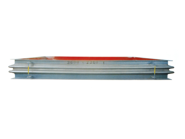
Metal rectangular expansion joint
Product introduction of metal rectangular expansion jointProduct Structure and C...
Learn more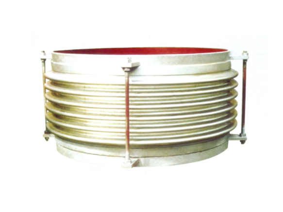
Universal corrugated expansion joint
The universal corrugated expansion joint is a kind of flexible compensation elem...
Learn more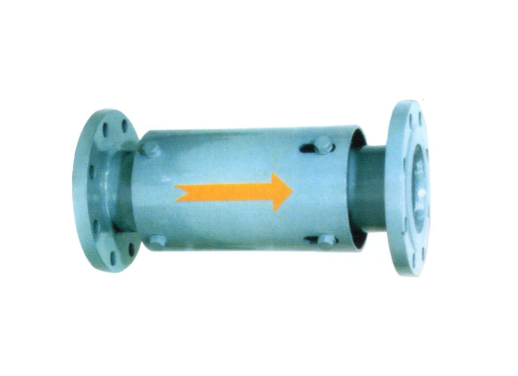
Single axial expansion joint
I. Structural compositionThe single axial expansion joint is mainly composed of ...
Learn moreCompensator, baffle door equipment · One-stop service process
From consultation to installation, we offer a full range of professional services
Consultation needs
The professional team will provide you with detailed product consultation and technical support to understand your specific needs
Scheme design
Provide personalized product design according to your specific needs to ensure the best solution
Manufacturing
Adopt advanced production equipment and technology and strict quality control to ensure excellent product quality
Installation and commissioning
Professional technicians provide on-site installation and commissioning services to ensure the normal operation of the equipment
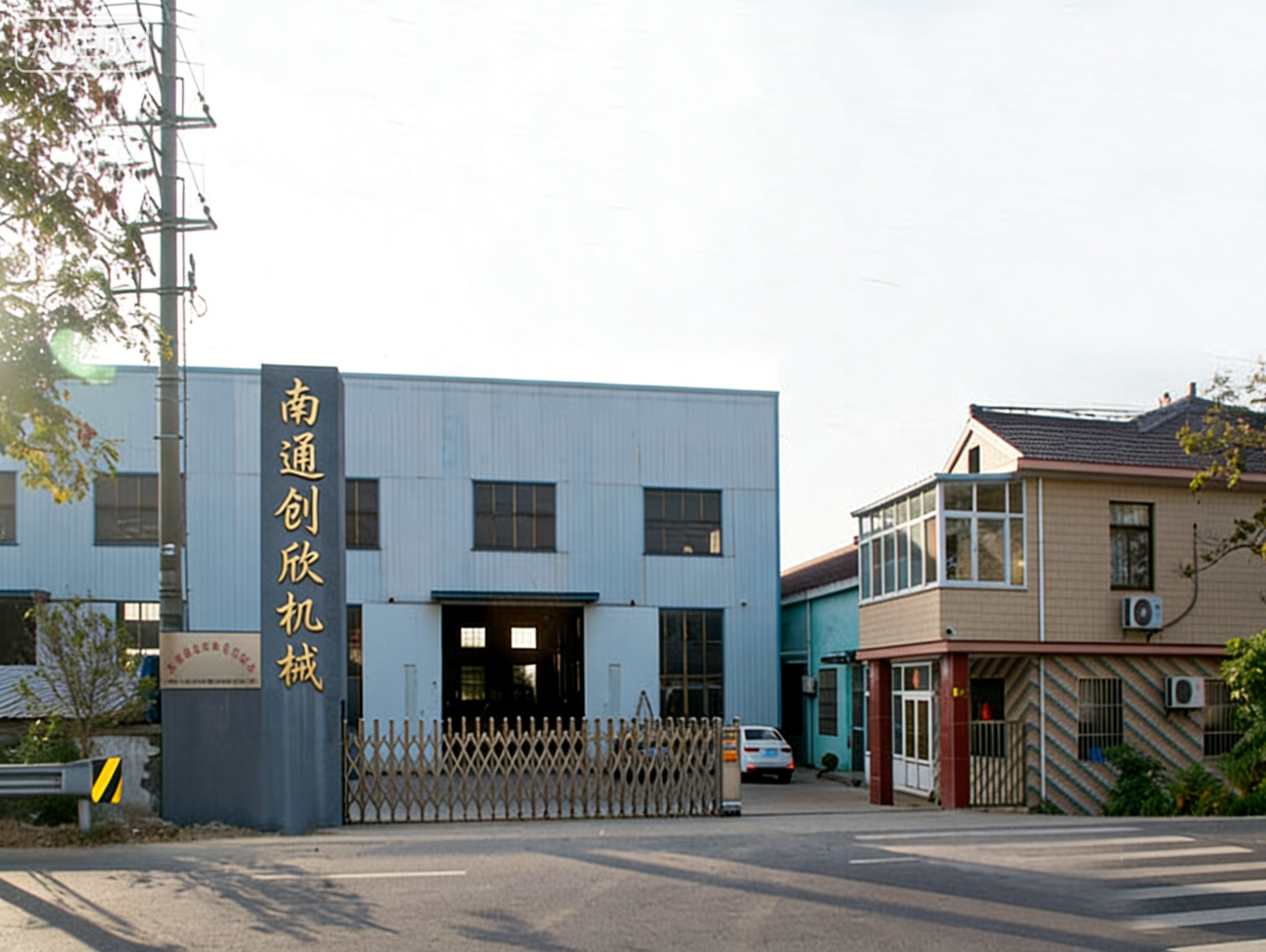
About Us
Nantong Chuangxin Machinery Co., Ltd. is located in the plain of central Suzhou, close to Nantong and Ningjingyan Expressway with convenient transportation, and less than 2 hours drive from Shanghai, Suzhou, Wuxi, Nanjing and other large and medium-sized cities.
The company is a comprehensive scientific and technological enterprise integrating design and development, production, product sales, installation and debugging. The company has successively communicated and cooperated with the National Cement Research Institute and the general contractor!
The company's main products are metal compensator (expansion joint), non-metal compensator (expansion joint), baffle door and other series products, providing excellent and cheap complete sets of equipment for the majority of users at home and abroad.
NEWS
Stay up-to-date with company and industry updates
Where are all stainless steel expansion joints used? How to choose? Practical Experience of Old Engineers
1. Where is the all-stainless steel expansion joint "all"? Material Co...
Metal Expansion Joints as: A Guide to Selection, Installation and Pit Avoidance for Common Failures
Why is it an expansion joint, not a corrugated compensator? — Differen...
Nonmetallic Compensator at Boiler Inlet: A Guide to Selection and Pit Avoidance and Field Practice
What is good about the boiler inlet non-metallic compensator? Find out...
How much can the non-metallic compensator extension joint hold? Don't be fooled by the name
How much can the non-metallic compensator extension joint hold? Don't ...
How long is the warranty period for non-metallic compensators? Don't be fooled by "3 years"
Warranty period is not shelf life-first understand the difference betw...
Non-metallic compensator service is good, but what is the advantage? Selection Record of a Pipeline Engineer
Choosing non-metallic compensator, the most afraid of manufacturers on...
Frequently asked questions
Answers to your frequently asked questions about compensators and baffle doors
How to Repair Metal Expansion Joints? Judge the type of fault first, then decide whether to repair or replace
Two days ago, I met a customer. On the phone, I was anxious to say that their factoryUniversal corrugated expansion jointThere was an air leak and asked if it could be repaired. I asked him to take a video first, and at a glance-there was a trachoma the size of a millet grain on the surface of the bellows, but the whole thing was not deformed, and the tie rod nut was not loose. In this case, repair welding can last for two years. But if the crack has already penetrated three or four waves, or the bellows is directly stuck, then sorry, the cost of repairing is higher than replacing.
SoHow to Repair Metal Expansion Joints?The core is one sentence: first find out the type of fault, and then decide whether to repair it partially or scrap it directly. Don't dismantle it as soon as you come up, and don't change it as soon as you leak, which is a waste of money.
First, find out the root cause of the fault-air leakage, stuck or deformation?
Before maintenance, the most taboo thing is to rely on feeling. You have to at least make a judgment with the naked eye and simple tools. Common faults fall into three categories:
- air leakage: The sound can be heard hissing, or use soapy water to paint welds, bellows peaks and valleys, and watch bubbling. The air leakage point is generally at the base metal of the bellows, the end weld, or the connection between the connection and the flange. LikeCorrugated expansion joint for power station industryHigh operating temperature, high pressure, air leakage is mostly fatigue crack, andMetal Corrugated Expansion Joints in Cement IndustryAir leaks are often due to perforations caused by dust wear.
- Stuck (Displacement Failure): The pipe does not expand or contract when it should be expanded or contracted, or the expansion joint is forcibly pulled into a straight line and cannot be pushed by hand. The tie rod nut is too tight, the guide tube falls off and sticks the bellows, or dust accumulates and scales inside, which will cause stuck. LikeHigh temperature axial expansion jointIf the guide tube in the tube falls off and hits the bellows directly, the movement is not small.
- deformation: The bellows has obvious twisting, uneven wave pitch and local bulging. This is often caused by over-displacement operation. You measure the actual displacement, and then compare it with the factory design value, which is clear at a glance.
If you judge these three situations correctly, it will be easier to handle later. If the judgment is wrong, it will be in vain if the cultivation is done.
2. Local damage of corrugated pipe: if it can be repaired, it will not be replaced, but it depends on the material and thickness
If it is only small trachoma or shallow crack, and the material is austenitic stainless steel of 304 or 316L, with a thickness of more than 0.5mm, it can be repaired. Note: Before repair welding, the damaged area must be polished clean to expose the metallic luster. Use argon arc welding, and the welding wire should be made of the same material or more corrosion-resistant (such as 316L welding wire). It must be smoothed after welding, otherwise it will become a new stress concentration point.
But if that thickness of the bellows is less than 0.3mm (such as someSpecial hose for vacuumOr under low pressurePTFE-lined hose), or the material is special alloys such as Hastelloy and Inconel, which ordinary welders can't handle at all. It is recommended to contact the manufacturer directly. There is another situation: the crack is at the root of the bellows (trough), where the stress is the largest, and the life after repair welding can't be long. It is better to replace it with a new one.
Metal rectangular expansion jointAndLarge diameter thick wall expansion jointMost of the corrugated plates are splicing welds, so attention should be paid to thermal deformation control when repairing welding, otherwise the more they repair, the more they leak.
3. The tie rod nut is loose or the guide tube falls off: adjust the minor problems yourself, don't screw it over
These kinds of problems seem small, but they are self-defeating when they are not handled well. Such asHow to adjust the tie rod nut of expansion joint? The standard practice is to confirm the design displacement first, and symmetrically loosen the adjustment nut with a wrench to restore the bellows to its free length. Don't screw it unilaterally, otherwise the expansion joint will twist. Many teachers screwed to death as soon as they came up. As a result, the bellows couldn't expand and contract normally and stuck directly.
Let's talk about the deflector falling off. The guide tube itself is fixed to the inner wall of the pipeline by bolts or spot welding. If it falls off, it will fall off and jam the bellows, or even be washed away by the medium and smash the downstream valve. During maintenance, open the manhole and re-weld or bolt the fallen guide tube. Be careful that the weld should not be higher than the surface of the guide tube, so as not to affect the flow of media. LikeDesulfurization flue gas baffle doorIn this kind of equipment, once the guide tube falls off, the slurry pours back into the bellows, and the corrosion rate doubles.
4. What circumstances must be scrapped? Fatigue crack, corrosion perforation, excessive displacement
Don't be reluctant. In some cases, forcibly repairing is planting mines.
- Fatigue crack: If the crack extends more than 3 waves along the bellows axial direction, or the circumferential crack length exceeds 1/4 of the circumference, it means that the material has been fatigued and will crack again soon after repair welding. Direct replacement, recommendedExternal pressure single axial expansion jointOrCompound hinge transverse expansion jointThis type of structure has better fatigue resistance.
- Corrosion perforationPerforations caused by pitting and intergranular corrosion often have only a small hole on the surface, but the surrounding metal has been embrittled. Use magnetic particle detection or coloring flaw detection. If you find dense micro-cracks, don't fix them. Especially for chemical pipelinesPTFE compensatorOnce the inner liner is perforated, the media will corrode the outer metal.
- Excess displacement: The actual operating displacement exceeds the design value by more than 120%, and the bellows has produced plastic deformation. Such asDirect buried (fully buried) type expansion jointOver-stretched, the wave pitch is uneven, and repair welding is useless at this time, because the bellows has lost its elasticity.
By the way,Service life of expansion jointGenerally, the design is 1000~2000 full displacement cycles, but many factories have not broken after ten or eight years of use, because the actual displacement is far less than the design value. If the limit is exceeded frequently, the life span will fall off a cliff.
5. How to accept after maintenance? Pressure test and displacement rebound are indispensable
It's not finished after repairing, you have to verify that it still works. Two steps:
The first step, the pressure test.Carry out hydraulic pressure test according to 1.25 times of the design pressure, hold the pressure for 10 minutes, and check whether there is any leakage on the surface of welds, flanges and bellows. Note: It must be thoroughly blow dried after the hydraulic test, esp.Double hinge expansion joint for air-cooled island vacuum pipelineThis kind of vacuum equipment, when the residual moisture is vacuumed, it will freeze and damage the bellows.
The second step is the displacement rebound test.Loosen the tie rod nut, push and pull the bellows by hand, see if it can smoothly expand and contract to the designed displacement, and whether it can rebound automatically after releasing. If the rebound fails to reach its original position, it means that there is a jamming inside, or the bellows has become unstable. ForCurved tube pressure balance expansion jointFor this type of balanced structure, it is also necessary to check whether the tie rod of the pressure balancing ring moves synchronously.
After these two steps, the maintenance is qualified.
6. Keeping an eye on a few details daily can save half of the trouble
After all, maintenance is a passive remedy, rather than prevention. If you keep an eye on the following points, the failure rate will be reduced by at least half:
- Deflector Wear Inspection: Open the manhole every six months, especially the flue gas system and pulverized coal pipeline. When the deflector is worn to less than half the original thickness, replace it in advance, don't wait for it to fall and smash the bellows. LikeNon-metallic expansion joint (fabric fiber expansion joint)Although there is no metal bellows, the deflector is equally afraid of wear.
- Periodic preloading of tie rod nuts: Not for you to tighten it, but to check if it is loose or rusty. ForLarge tie rod expansion jointEvery three months, use the torque wrench to re-tighten according to the design value to prevent the nut from loosening due to vibration.
- Displacement monitoring: Mark the scale on the expansion joint and record the amount of displacement at each shutdown. If you find that a displacement suddenly becomes larger or smaller, it means that the pipe support may be offset. Let's sayStraight pipe pressure balanced expansion jointIf the displacement is abnormal, there is a high probability that the main fixation bracket is loose.
- Heat preservation and corrosion protection: Expansion joints for outdoor installation, especiallyHigh temperature axial expansion jointAfter the insulation layer is damaged, rainwater enters, and the corrosion rate is astonishing. Regularly check the sealing condition of the insulation layer and repair the damaged areas. Also, don't let the corrosive liquid drip directly onto the bellows.
Okay, so aboutHow to Repair Metal Expansion Joints?I was detailed enough. You go back and compare your own expansion joint, look at the type of fault first, and then decide whether to repair or replace it.
Two days ago, a customer from a power station called, and his tone was very urgent, saying that a corrugated expansion joint on their pipeline was leaking and perforated. Asked me if I could just weld it on and make do. This kind of question is too common in the industry, but the answer is really not simply "can" or "can't". What about perforated metal expansion joints? Whether it is repaired or replaced depends on the reason and location of the perforation, and which expansion joint you are using. Let's talk about the conclusion first: blind repair welding will in all likelihood happen bigger things.
The reasons for perforation vary
The most common is corrosion-chloride ions, sulfides in the medium, or high-temperature oxidation. For example, the corrugated expansion joint used in the power station industry is prone to high-temperature oxidation and thinning on the outer wall under high-temperature flue gas for a long time, and finally perforation. Where is the metal corrugated expansion joint in the cement industry, dust abrasion is the main cause. In another case, the tie rod nut is not adjusted properly during installation, which causes the bellows to bear undue torsion or lateral displacement, and fatigue cracks eventually develop into perforations. Think about it, if you weld indiscriminately, there are still media residues sandwiched in the cracks, and it will be virtual when welded.
By the way, there is another reason for perforation that many people ignore-the deflector failure. The specific function of the expansion joint guide tube is to protect the bellows from high-speed medium erosion. Once the guide tube is damaged, the medium directly impacts the bellows, and the local erosion speed can be several times faster. At this time, even if you weld the perforation, the inner wall will continue to thin, and it will leak again soon.
Is there a temporary emergency solution? Yes, but the conditions are harsh
For example, the circulating water pipeline with low pressure and normal temperature has a small perforation (the diameter does not exceed 5mm), so it can be temporarily blocked with a rubber gasket covered with a fixture, or cold solder (metal repair glue) can be used for emergency response. But only if you have to confirm that the medium temperature does not exceed the temperature resistance range of the glue, and the pressure is below 0.5MPa. Don't do this on high-temperature and high-pressure steam pipelines-steam pipelines belong to pressure pipelines, and they can be repaired and welded directly after perforation. Local stress concentration may make the bellows explode.
Many people think that the expansion joint and the compensator are two different things, so they treat them according to the ordinary pipeline repair welding process, and as a result, the elasticity of the corrugation is welded away. Actually, is the expansion joint the same as the compensator? The answer is one thing, it's just called differently. The bellows itself absorbs displacement by elastic deformation, and the welding repair area will harden and lose elasticity, so this expansion joint is basically wasted.
When do you have to change? Don't hesitate to replace it with a new one
Let's put it this way, as long as the diameter of the perforation exceeds 1/3 of the wall thickness of the bellows, or the perforation appears in fatigue sensitive areas such as peaks and troughs, don't hesitate to replace it with a new one directly. EspeciallyLarge diameter thick wall expansion joint、External pressure single axial expansion jointFor those with high pressure, the weld area will become a new weak point after repair welding, and the risk of creep fracture will double. Also, if the perforation is associated with damage to the guide tube, it must be replaced as a whole. Once the guide tube is broken, the internal erosion will be accelerated, and the welding repair is a waste of effort.
And guess what? Some customers feel that it is expensive to replace the expansion joint, so they have to repair welding to save money. As a result, it took two days. On the third day, the weld cracked, and the medium sprayed out and almost injured people. The loss of one equipment shutdown is much more than replacing the expansion joint. Safety first, don't gamble on your luck.
Prevention is more important than remedy
Corrosive medium, preferredPTFE-lined hoseOrPTFE compensator; High temperature flue gas pipe, forHigh temperature axial expansion jointInner lining with temperature-resistant coating; Dusty cement line, useMetal Corrugated Expansion Joints in Cement IndustryOrRectangular non-metallic expansion joint(the kind of fabric fiber), the latter is low replacement cost and convenient maintenance.
The direction of the arrow of the expansion joint points to the direction of the medium flow, and the tie rod (the role of the expansion joint tie rod is to limit excessive tension) can only be loosened after the pipeline pressure test. In daily inspection, check whether there are rust pits and peeling on the corrugated surface, and cooperate with the inspection cycle of non-metallic expansion joints, at least twice a year.
Metal expansion joint perforation, don't treat it as an ordinary leak. It is like a spring. Welding repair is equivalent to tying a knot on the spring. Do you think this spring can still work properly? Leave professional matters to professional people-if you are unsure of the cause of the perforation, or are unsure whether it can be repaired, contact the manufacturer directly to send the on-site photos and media parameters.
Mistaken selection is the number one killer of short lifespan-material and construction determine how many years you will last
Two days ago, I met a customer who complained that the expansion joint in their factory leaked after two years. When I removed it, the bellows were rotten. Ask about the working conditions-high-temperature steam pipeline, with a pressure of 1.6MPa and a temperature of 350℃. As a result, the general-purpose corrugated expansion joint was chosen at the beginning, and the material was 304 stainless steel. Isn't this seeking death?
The matter of model selection, to put it bluntly, is "what horse matches what saddle". High-temperature working condition honestly high-temperature axial expansion joint, the material must be Inconel 625 or at least 321 stainless steel; For corrosive media, such as desulfurization flue gas, you have to consider lining PTFE hoses or non-metallic expansion joints (fabric fiber expansion joints), and even rubber compensators can carry them for a while. In cases where particle erosion is serious, such as air ducts in cement industry, metal corrugated expansion joints in cement industry must have wear-resistant guide tubes, otherwise they will be worn out in less than half a year.
Structurally, don't be sloppy. For pipelines with large axial displacement, straight pipe pressure balance expansion joint or compound straight pipe bypass pressure balance expansion joint is the positive solution; If you need to absorb lateral displacement, compound hinge transverse expansion joint or curved tube pressure balance expansion joint is right. Choosing the wrong type is like letting a sprinter lift weights, and scrapping is a matter of time.
The "invisible killer" of the installation link: the draw rod is not adjusted in place, the guide tube is installed backwards, and no matter how good the expansion joint is, it is useless
You can sit back and relax when you choose the right equipment? That's naive. The pits in the installation link, each deeper than the last. The most common one is that the tie rod nut is not adjusted properly. The function of the expansion joint tie rod is to limit the over-stretching or over-compression of the bellows, but many installation teams directly lock the tie rod, or simply don't dismantle the transportation fixtures. And guess what? As soon as the pipeline heats up, the expansion joint has no space to compensate, and the bellows is directly bulged and scrapped. The correct way is to remove the transport screw after installation, and then adjust the tie rod nut according to the compensation amount. For details, refer to the article "How to adjust the tie rod nut of expansion joint" in our station.
There is a more hidden problem-the deflector is installed backwards. The specific function of the expansion joint guide tube is to guide the flow direction of the medium and protect the bellows from scouring. However, when the direction of the arrow is reversed, the medium directly impacts the root of the bellows, and the rate of corrosion and wear doubles. Remember: The direction of the arrow must coincide with the direction of the media flow. Don't laugh, at least 30% of the installers on the site will make this mistake.
Wear and corrosion in operation: medium temperature, particle erosion, chemical attack, how many of these pits have you stepped on?
During normal operation, the expansion joint can't be laid flat just by installing it. If the medium temperature exceeds the design value of 10℃, the fatigue life of the bellows may be directly discounted by 50%. Particle scour? That's even more like cutting meat with a soft knife. Some cement plants use ordinary metal rectangular expansion joints, and there is no guide tube inside. After half a year, the wall thickness of the bellows is ground from 3mm to 0.5mm. Do you think it can be perforated?
Chemical attack is more headache. The acid condensate in the desulfurization system is a fatal blow to the metal bellows. At this time, either choose a PTFE hose or PTFE compensator, or use a non-metal expansion joint (rubber PTFE compensator is also OK), but we must pay attention to the rubber aging problem. By the way: Is there pitting corrosion and intergranular corrosion on the surface of the expansion joint in your factory? If so, it means that there is a problem with material selection, so change it as soon as possible.
Regular inspection is not a formality: corrugated pipe cracks, rubber aging, non-metal layer peeling, early detection and early treatment
Many factory inspections are to walk around with a flashlight and see nothing. In fact, there is a precursor to the failure of the expansion joint. Fine cracks or "orange peel"-like deformation appear on the surface of metal bellows, which indicates that it is close to the fatigue limit. Rubber compensator or non-metallic expansion joint, pay attention to whether the surface has hardened, cracked, or delaminated peeling. Especially rubber, affected by ozone and ultraviolet rays, has a life span of three to five years. When the time comes, it should be changed. Don't wait for it to leak before stopping.
Also, check for any changes in the pre-tightening forces of the tie rods and bolts. After the expansion joint has been running for some time, the tie rod may loosen, causing the bellows to offset. If the bellows is found to have eccentric wear marks, it means that the pipe support may sink or the compensation direction is wrong. Early detection and early adjustment, it's still too late.
Environmental factors alone? Heat preservation, support and drainage are done correctly, and the life will be doubled directly
Environmental factors are often overlooked, but are often the last straw that crushes the camel. For example, the expansion joint installed outdoors does not do heat insulation, and the metal brittleness increases at low temperatures in winter, so the bellows is easier to crack. Another example is the expansion joint on the steam pipeline. If there is no reasonable drainage design, the condensed water will accumulate at the trough, forming a "water hammer", which will impact and damage the bellows. How to solve it? Set a drain valve at a low position, or choose a sleeve-type pipe expansion joint with drain structure.
Support is also critical. The expansion joint itself does not bear the weight of the pipe, and guide brackets and fixed brackets must be set nearby. Many sites use the expansion joint as a pipe support, but as a result, the bellows is flattened and scrapped in three months. Think about it, is it worth an expansion joint worth tens of thousands of dollars to be scrapped in advance because several brackets worth several thousands of dollars were not done properly?
When to change hard bracing: Precursor judgment of failure and targeted prevention strategies
Expansion joints are not maintenance-free for life. If the following signals appear, change them quickly and don't take chances: First, the bellows has obvious cracks or perforations; Second, the fabric layer of the non-metallic expansion joint peels off in a large area, and the internal thermal insulation cotton or steel wire mesh can already be seen; Third, the surface of the rubber compensator is hardened to the point that it can't be pressed, or there are bubbles bulging; Fourth, the whole expansion joint is obviously distorted, which indicates that the displacement of the pipeline has exceeded the design range.
According to the medium characteristics and working conditions, select the right type in advance (such as special products such as corrugated expansion joints for power station industry, double hinge expansion joints for air-cooled island vacuum pipelines, etc.), strictly implement the specifications during installation, and regularly check and adjust in time during operation. If conditions permit, install displacement monitoring sensors at key positions, and watch the expansion and contraction of the bellows in real time, and you will have a bottom in your heart.
To put it bluntly, there are three words to prolong the life of expansion joints-select, install and raise. Choose the right thing, install it well, and maintain it diligently. To achieve these three points, it is not a dream to serve for more than ten years.
Non-metallic compensator leaking? Don't be in a hurry to change, try these steps to fix the leak first
I answered a phone call two days ago, and the customer said that the non-metallic expansion joint of their dust removal system began to smoke after half a year. When disassembled, the particulate matter in the smoke grinds a hole in the skin-this kind of thing is too common in cement and electric power industries. The non-metallic compensator (also called fabric fiber expansion joint) is leaking. Your first reaction is to replace it with a new one? Don't worry. Find out the leak point first. 80% of the cases can be fixed on site.
Where's the leak? Three common locations
Non-metallic compensator is used in flue gas pipeline and desulfurization system. The medium temperature is high and corrosiveness is strong, and the leakage is basically in three positions: one is the overlap joint between layers, the other is the sealing surface at the connection of flange, and the third is the riveting point or weld between the guide tube and the skin. And guess what? Many times it is not the skin itself that is broken at all, but the bolts are loose-the flange surface leaks, which can be solved by tightening. So the first step is not to rush to buy new pieces. First, take a flashlight and brush it with soapy water to see where the bubbles come from.
The medium contains sulfur or strong acid and alkali, and the sealing gasket becomes brittle after aging, and it will break when touched. At this time, you have to judge the type of leak: is it pitting perforation (small hole), sealing surface failure, or overall fatigue cracking? The countermeasures are completely different in different situations.
Preparation before mending leaks: Wrong material selection is equal to dry for nothing
Don't put any glue on it. This site hasrubber compensator、Rubber PTFE compensator、Non-metallic expansion jointAnd other products, leak repair materials must match the working conditions. High-temperature flue gas pipeline uses high-temperature resistant silicone rubber or fluororubber sealant, and ceramic fiber repair materials have to be replaced when the temperature exceeds 300℃. If the medium contains acid and alkali, use PTFE sealing tape, refer to this sitePTFE-lined hoseCorrosion resistance ideas.
Be sure to clean up before repairing the leak. Oil, dust accumulation and old glue layer have to be shoveled off to expose fresh substrate. Wipe it with acetone or alcohol, and wait until it is completely dry before starting. Otherwise, if you make it up, it will drop in two days.
By the way, if the flange surface leaks, check the bolts first-in many cases, it's just thermal expansion and contraction that causes loosening. Just take a torque wrench and re-tighten it according to the original torque. Don't get major surgery right up there.
Three Methods of Leakage Mending in Actual Combat
Method 1: Small perforations or cracks are patched with temperature-resistant cement + glass fiber cloth in multiple layers.Apply the glue to the break first, stick the cut fiberglass cloth, and then scrape it flat with a scraper to ensure that there are no bubbles. Apply one layer until it dries (usually 4-6 hours), then apply a second layer, at least three layers. Finally, brush a layer of temperature-resistant sealant on the outer surface to form a protective film. This method is suitable for perforations less than 20 mm in diameter.
Method 2: The local damage area is large, and the skin of the same material is cut and replaced.This site has ready-madeNon-metallic expansion jointSkin material, cut according to the damaged area, overlap width at least 50mm. Apply high-temperature-resistant adhesive to the overlap surface, and rivet and fix it with stainless steel press strips and self-tapping screws after pasting. Note that the spacing of the pressing strips should not exceed 150mm, and the riveting points should be staggered out of the original structural holes to avoid stress concentration.
Method 3: Total Outsourcing? Don't mess around.Someone asked if you could just wrap a metal compensator on the outside? No way. This site hasHigh temperature axial expansion joint、Universal corrugated expansion jointHowever, these metal parts are used for pipe displacement compensation, and their structure is completely different from that of non-metallic skin. Hard wrapping will limit thermal displacement, but accelerate damage. A more reliable way is to customize a short-joint non-metallic expansion joint to replace the damaged section. The size should match the original pipeline. Just provide the diameter, temperature, pressure and displacement when ordering.
Testing and routine maintenance after leak repair
It can't be put into operation directly after repairing, so do the airtightness test first. Brush soapy water or foaming agent on the repair area, introduce 0.05~0.1MPa compressed air (the design pressure of non-metallic compensator is low, so don't overpressure), and observe whether there are bubbles. If there is no air source, feel the air leak point with your hands after running, or use infrared thermal imaging to see the temperature abnormality-the temperature at the leak will be significantly lower.
Check the skin surface quarterly for blistering, delamination, and hardening. Especially in cement plants,Metal Corrugated Expansion Joints in Cement IndustryNext to the non-metal segment, dust wear is fatal. It is recommended to establish a ledger, record the location of each leak and the number of repairs, and accumulate data to judge when to completely replace it.
When should I give up patching and replace it with a new one?
If the same part is repaired more than twice, or the leakage area exceeds 30% of the total area, don't worry about it. The design life of non-metallic compensator is generally 3~5 years, and the aging will be accelerated by temperature, corrosion and mechanical fatigue. Also note that if the leak occurs in connection with this siteFlue gas baffle door、Electric plug-in insulation doorWhen connecting, consider whether the system vibrates too much. Vibration will cause fatigue cracking of the skin, which is useless. You have to install damping or switch to non-metallic expansion joints with reinforcing nets.
Don't save hundreds of dollars to make up for the leakage. As a result, the leakage expands and leads to the shutdown of production-the loss starts with tens of thousands of dollars. If you need to change, you will not lose money in the general ledger.
Metal expansion joint desoldering? Don't hurry to scold the manufacturer, the problem may lie in this
Two days ago, I met a customer who said that the metal expansion joint weld of their pipeline was cracked, and asked me if the quality was not good. Alas, who is not in a hurry when it comes to such things-media leakage, production line shutdown, or safety accidents. But let's say, don't rush to throw the blame on the manufacturer. For the problem of desoldering, we must first look at where the welding is located. Is it the bellows and end pipe connection? Or a deflector weld? Or is it a tie rod mount? The causes of desoldering in different positions vary a hundred and eighty thousand miles.
The cracking of the circumferential weld between the bellows and the end pipe is most likely due to fatigue or stress concentration. If the weld of the guide tube is cracked, it is mostly because the guide tube is worn through by the medium or the guide tube is installed backwards, causing the airflow to directly scour the weld. Tie rod bearing desoldering? You have to check whether the tie rod nut is loosened during installation, and whether the limit is regarded as a fixed support. And guess what? Many so-called "quality accidents" were checked over and over again. Either the installation team was fooling around, or the selection didn't match the working conditions at all.
The three most common pits for desoldering
First, fatigue.The pipeline system expands and contracts thermally every day, and the expansion joint expands and contracts repeatedly. Once the stress concentration at the weld exceeds the allowable value, cracks will slowly grow out. Especially the large-diameter thick-walled expansion joint or high-temperature axial expansion joint, the more extreme the working condition, the more sensitive the fatigue life. For example, the temperature of high-temperature flue gas pipelines in the cement industry often fluctuates above 400℃. Every time the bellows expands and contracts, the welds accumulate damage.
Second, corrosion.When there are chloride ions and sulfide in the medium, the weld seam will be corroded preferentially, and the strength will drop linearly. The expansion joint behind the desulfurization flue gas baffle door has a bad corrosion environment. If the right material is not selected or the corrosion resistance treatment is not done, the weld will become slag in less than half a year.
Third, the installation error.When leaving the factory, the tie rod nut was not loosened, the guide tube was installed backwards, and the cold drawing amount of the pipeline was not enough... These operations caused additional stress to be fully pressed on the weld. Many customers complained that "it took three months to desolder". As a result, when they went to the scene, they found that the direction of the guide tube arrow pointed to the opposite direction of the medium flow, and the airflow directly hit the bellows. Tsk, is this pot manufacturer wronged?
What about that?
Let's see the working conditions first. If it is a pipeline at normal temperature and low pressure, such as a general-purpose corrugated expansion joint, the cracking of the weld joint is probably a problem of the welding quality itself-the current is excessive, the welding electrode is wrong, and the groove is not handled properly. You have to re-weld if you should cut it off and re-weld it. Don't feel distressed. However, if it is a high-temperature steam pipeline or a high-temperature flue gas pipeline in the cement industry, desoldering is often a wrong selection. At this time, we have to consider changing the high-temperature axial expansion joint or the external pressure single axial expansion joint, so that the bellows can avoid the high-temperature area. Another situation: the displacement of the pipeline is too large, and the general-purpose type can't bear it at all, so it is necessary to use the double hinge transverse expansion joint or the straight pipe pressure balance expansion joint to share the stress.
On-site emergency treatment is also particular. Small cracks can be repaired in non-critical parts, but they must be welded with the same material electrode, preheated and controlled cooling speed. If the bellows itself is cracked, don't repair welding-the wall thickness of the bellows is thin, and it will burn through as soon as it is repaired, so replace it directly. In addition, it should be noted that before repair welding, check whether the guide tube is in good condition. If the guide tube is also worn out, the medium will directly wash the inner wall of the bellows, and desoldering is only a prelude. When replacing, it is best to check the adjustment status of the expansion joint tie rod nut simultaneously to ensure that the pre-tension or pre-compression meets the design requirements. As for how to adjust the tie rod nut? After screwing the nut to the limit position, reverse back half a turn to one turn, so that the expansion energy saving can expand and contract freely. Look at the design drawings for specific values, don't screw them blindly by hand feel.
Prevention is really worry-free
The selection stage is not cheap. When providing information to the design institute, write clearly the temperature, pressure, displacement and corrosive medium. For example, the expansion joint behind the flue gas baffle door has a high sulfur content in the medium, so corrosion-resistant alloy or PTFE-lined scheme must be used. In the installation stage, be sure to look at the direction of the arrow on the expansion joint (flow direction mark), and one end of the guide tube faces the direction of the medium. During the operation stage, check the appearance of the weld regularly, tap and listen to the sound, and do penetration testing if conditions permit. Don't forget, the life of the expansion joint is directly tied to maintenance-you let it run over the limit, and it will strike sooner or later.
In the final analysis, 80% of the desoldering of metal expansion joints are not deliberately cut corners by manufacturers. Find the root cause, prescribe the right medicine, change the type, repair the welding, don't curse your mother as soon as you come up. Pipeline safety depends on the cooperation of three rings of selection, installation and maintenance, and one less ring will lead to moths.
Contact Us
Your consultation and cooperation are always welcome
Company Address
Haian Economic and Technological Development Zone, Nantong City, Jiangsu Province
Contact Number
(+86)13142668488
info@jsbcq.net
Working hours
Monday-Friday :8:00 - 17:30
Saturday :9:00 - 16:00
Sunday :Rest