Specialized in manufacturing compensators, expansion joints, baffle doors
A comprehensive scientific and technological enterprise integrating design and development, production, product sales, installation and debugging
Specialized in the production of metal compensator, non-metal compensator, baffle door equipment for 18 years
Product Center
Specialized in manufacturing a variety of high-quality industrial equipment to meet your diverse needs
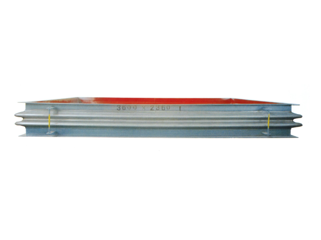
Metal rectangular expansion joint
Product introduction of metal rectangular expansion jointProduct Structure and C...
Learn more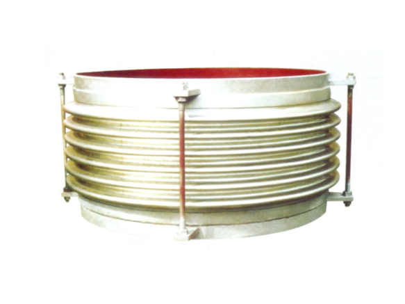
Universal corrugated expansion joint
The universal corrugated expansion joint is a kind of flexible compensation elem...
Learn more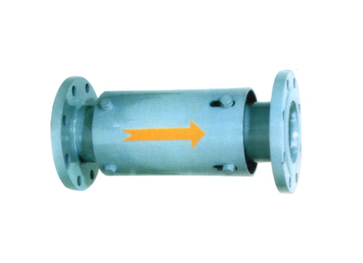
Single axial expansion joint
I. Structural compositionThe single axial expansion joint is mainly composed of ...
Learn moreCompensator, baffle door equipment · One-stop service process
From consultation to installation, we offer a full range of professional services
Consultation needs
The professional team will provide you with detailed product consultation and technical support to understand your specific needs
Scheme design
Provide personalized product design according to your specific needs to ensure the best solution
Manufacturing
Adopt advanced production equipment and technology and strict quality control to ensure excellent product quality
Installation and commissioning
Professional technicians provide on-site installation and commissioning services to ensure the normal operation of the equipment
About Us
Nantong Chuangxin Machinery Co., Ltd. is located in the plain of central Suzhou, close to Nantong and Ningjingyan Expressway with convenient transportation, and less than 2 hours drive from Shanghai, Suzhou, Wuxi, Nanjing and other large and medium-sized cities.
The company is a comprehensive scientific and technological enterprise integrating design and development, production, product sales, installation and debugging. The company has successively communicated and cooperated with the National Cement Research Institute and the general contractor!
The company's main products are metal compensator (expansion joint), non-metal compensator (expansion joint), baffle door and other series products, providing excellent and cheap complete sets of equipment for the majority of users at home and abroad.

NEWS
Stay up-to-date with company and industry updates
rjx Nonmetallic Expansion Joint: Why are Power Plants and Cement Plants Using It?
What are rjx non-metallic expansion joints? What is the difference bet...
How to choose metal expansion joint flange bolts? Materials, Specifications and Installation Pit Avoidance Guide
This flange bolt thing, it looks unremarkable, but it is the last line...
How to choose non-metallic expansion joints in steel mills? Old drivers talk about those easy pits
Why steel mill pipes can't be separated from non-metallic expansion jo...
How to set the temperature standard of metal expansion joint? Don't just look at the material, these are the key points
Two days ago, I met a customer who asked me with a selection table, "M...
Pressure in metal expansion joint: If the wrong pressure level is selected, the pipeline system may be directly scrapped
What the hell does internal pressure matter? — — Core parameters of ex...
Metal expansion joint installation reason: How many winters can the plumbing system last without installing it?
Thermal expansion and contraction are the number one killer of piping ...
Frequently asked questions
Answers to your frequently asked questions about compensators and baffle doors
1. The core basis of grading: pressure, temperature and compensation amount
After doing pipeline compensation for so many years, the most asked thing is: "How to divide the grade of metal expansion joints?" In fact, in the final analysis, there are three hard indicators: pressure, temperature and compensation amount. These three parameters basically lock in which level of product you should use.
Let's start with stress. The wall thickness, number of layers and wave height of bellows used in low pressure (0.1~0.6MPa) and high pressure (≥2.5MPa) are completely different from the same concept. For example, the general corrugated expansion joint has a general design pressure within 1.0MPa; However, the corrugated expansion joint used in the power station industry is 2.5MPa or even higher at every turn, so the corrugated pipe must be multi-layered, reinforced ring, and even armored. The pressure level directly determines the safety margin and fatigue life.
The temperature is tougher. 304 stainless steel can hold up to 100℃ at room temperature, but above 600℃, you have to use superalloys (such as Inconel 625), and you have to consider creep strength. Two years ago, a cement factory customer installed a high-temperature axial expansion joint on the kiln tail flue, with a nominal temperature of 800℃. As a result, ordinary 304 material was selected, and it cracked in three months-the wrong temperature grade was selected, which was equal to dry for nothing.
The amount of compensation is interesting. Axial compensation, lateral compensation and angular compensation, the compensation capabilities corresponding to different structural forms are far different. The straight pipe pressure balance expansion joint mainly absorbs axial displacement, while the compound hinge transverse expansion joint specializes in transverse displacement. The bigger the compensation amount is not the better. A large compensation amount means that the bellows is longer and has more wavenumbers, so the stiffness will come down and it is easy to become unstable. Therefore, when selecting a grade, the compensation amount must match the stiffness.
2. Looking at the grade from the standard: national standard, industry standard and manufacturer definition
When it comes to standards, many purchases say "just follow the national standard", but the national standard is actually very fine. The national standard for metal expansion joints is mainly GB/T 12777 (General Technical Specifications for Metal Bellows Expansion Joints), but don't expect this standard to cover all scenarios. For example, for metal corrugated expansion joints in cement industry, you have to refer to JC/T 967 (metal corrugated expansion joints for cement industry pipelines); Corrugated expansion joints used in the power station industry will involve DL/T 5185 (Technical Regulations for the Design of Bellows Compensators for Pipelines in Thermal Power Plants). The non-metallic expansion joint has JB/T 12235-2015, which is different from metal and non-metal, and the grading logic is different.
Manufacturer-defined grades are even more interesting. Domestic first-line brands, such as the products listed on our station, all have internal code names. For example, the general-purpose corrugated expansion joint is divided into PN0.6, PN1.0 and PN1.6 according to the pressure when it leaves the factory; However, it is also PN1.6. Different manufacturers may have differences in the number of bellows layers, the wall thickness of the end tube and the material of the guide tube. Therefore, it is not enough to only look at the "pressure level" of the manufacturer's trademark, but also the corresponding structural details.
For a desulfurization flue gas baffle door project, "Expansion joint grade: PN1.0, temperature resistance 200℃" is written on the drawings of the design institute. Results During on-site installation, it was found that there was a large amount of condensed acid in the flue gas, and 304 couldn't bear it at all. Finally, it was replaced with PTFE-lined hose, and the grade was redefined from the perspective of materials-this incident reminds us that the standard grade is only the foundation, and the "soft parameters" of medium corrosiveness and medium phase state are the real hidden grade lines.
3. Typical products corresponding to different grades: from general-purpose to power station/cement industry specific
Don't copy books about grading, it depends on the actual application scenarios. Let's pull out the product line and compare it:
- General scenario of low pressure and low temperature:Universal type corrugated expansion joint, metal hose, rubber compensator. The design pressure of these products is generally ≤1.0MPa and the temperature is ≤300℃, which is suitable for HVAC, water supply and drainage, and general industrial pipelines. Typical features are single-layer bellows, no guide tube or simple guide tube, cheap and frequent change.
- Medium-voltage and medium-temperature utilities:High temperature axial type expansion joint, external pressure single type axial type expansion joint, sleeve type pipe expansion joint. These products can have a pressure of 2.5MPa and a temperature of about 450℃, which are commonly used in steam pipelines and thermal pipe networks. Note that there will be a guide tube here, whose function is to prevent the high-temperature medium from directly washing the bellows-the specific function of the expansion joint guide tube, as specifically mentioned in our Q&A, is the key component to protect the bellows from high-speed fluid wear.
- High pressure and high temperature working conditions:Corrugated expansion joints for power station industry, metal corrugated expansion joints for cement industry and directly buried (fully buried) expansion joints. The pressure of the main steam pipeline of the power station is 10MPa, and the temperature exceeds 600℃. It must be designed with multi-layer bellows + external pressure balance. The flue gas temperature at the outlet of rotary kiln in cement industry is high and dusty, so it is necessary to use wear-resistant guide tubes and high-temperature resistant alloys.
- Special Structure:Double hinge transverse type expansion joint, curved tube pressure balance type expansion joint, air-cooled island vacuum pipe double hinge expansion joint. These are in the "custom-on-demand" rating, there are no standard models, and they must be designed one by one according to the pipe stress analysis.
Can I use the general-purpose one for power station projects? Of course not, let alone that industry standards don't allow it, and the materials themselves can't bear it. The level is wrong, it either leaks or explodes, and there is no intermediate option.
4. Pits that are easy to step on when selecting grades: the influence of material, stiffness and guide tube
Material selection only depends on pressure and not temperature. The common mistake is the stainless steel bellows of PN1.6, which works at 500℃, and thinks it's okay-in fact, 304 starts to accelerate oxidation above 425℃, so it is recommended to use 321 or 347. Therefore, when selecting a grade, the material grade must be confirmed separately.
Ignore stiffness. The stiffness and calculation formula of bellows are explained in detail on our site, but many selection personnel only look at the compensation amount. When the compensation amount is large, the stiffness will be small, and the force feedback of the pipeline on the equipment will become larger, which may pull out the equipment joint. This thing of stiffness determines that the expansion energy saving can't be "soft" enough to absorb displacement without transmitting excessive thrust. If conditions permit, let the manufacturer provide the stiffness value, and then do the pipeline stress calculation.
The guide tube is reversed or not installed. The function of the guide tube is not only to guide the flow, but also to reduce the fluid excitation and prevent the deposition of particles. However, in some projects, in order to save costs, the guide tube was removed. As a result, the inner wall of the bellows was blown away by high-speed steam, and it leaked in one year. Conversely, the deflector cannot be thickened at will-too thick will increase the local stress and lead to a decrease in the fatigue life of the bellows. It's a balancing point.
Two days ago, I met a customer who made gas turbines, and chose a special vacuum hose for use in the exhaust pipe. The grade was enough, but there was no guide tube. As a result, the particulate matter in the flue gas wore the bellows out. Alas, such lessons are all too common.
5. Practical suggestions: How to determine the grade of expansion joint according to working conditions
After so much verbose, here are some steps that can be used directly:
Step 1: List the working condition parameters.Media, pressure (design/operating pressure), temperature (design/operating temperature), type of displacement (axial/transverse/angular) and amount of displacement, nominal diameter of pipe.
Step 2: Determine the pressure rating.According to the table of GB/T 12777, find the number of bellows layers and wave height corresponding to DN and design pressure. Note: The allowable stress will be reduced at high temperature, so the pressure level should be corrected according to the high temperature working condition.
Step 3: Select the structural form.According to the displacement type: axial displacement, select straight tube pressure balance expansion joint or general type; Lateral displacement selection compound hinge transverse type; Pressure balance type of angular displacement curve selection tube; For large diameter and low pressure applications, sleeve-type pipe expansion joint or multi-wave type can be considered.
Step 4: Check the material..Temperature Step 5: Confirm whether you want a guide tube.If the medium flow rate is> 10m/s and contains particles, or the medium temperature is> 400℃, a guide tube must be added. The material of the guide tube is generally the same or higher than that of the bellows.
Step 6: Find the manufacturer to confirm the stiffness.Especially in scenarios where the pipeline is sensitive to the thrust of the equipment, such as connecting steam turbines and compressors, the greater the stiffness, the greater the thrust, which may push the base of the equipment.
In fact, how to divide the grade of metal expansion joint? In the final analysis, it is these three dimensions: load (pressure + temperature + displacement), environment (corrosion + wear + scour), and function (safety + life). You sort out these three points, and you can't go wrong with your selection. If you are still worried, just talk to our engineer with the parameters. Don't slap your forehead to set the grade-after all, the cost of installing this thing and then dismantling it is not a little.
Excessive limit is not just "screwing too tight" as simple
Two days ago, a buddy from a thermal power plant complained to me that their power station industry leaked after installing corrugated expansion joints for only three months. When removed, the limit nut is pressed against the end plate, and the bellows is directly pulled into an "eight" shape. I am too familiar with this scene-many people's first reaction is that the quality of the expansion joint is not good, but in fact, the root is most likely at the limit.
The limiting devices (tie rods, nuts, ear plates) were originally designed to protect the bellows from excessive stretching or compression during transportation or installation. However, if you regard the limit as a dead block, or the amount of pre-compression/pre-stretching is not accurate during installation, the displacement direction changes as soon as the pipeline runs, and the limit changes from "bodyguard" to "shackle". And the result? The actual displacement of the bellows exceeds the design value, which ranges from corrugation instability and weld cracking to scrapping of the whole expansion joint or even pulling off the pipe. Don't ask me how I know-I have been in this business for more than ten years, and I have seen more than I have cultivated.
The root is mostly in the installation stage, so don't rush to throw the pot to the product
"The cold tightening amount is adjusted according to the design value", but how many on-site workers screw it directly to the end to save trouble? Or a general-purpose corrugated expansion joint was selected during the selection, and as a result, the actual thermal displacement of the pipeline was 30% larger than the design value, so the limit was naturally "stuck". There is also a common pit: the pipe support is loose or the foundation sinks, which leads to the deviation of the displacement direction, and the limiting device becomes the main stress point instead. And guess what? 90% of cases can be solved by adjusting the tie rod nut without replacing new parts at all.
So don't doubt the product when you come up. Ask yourself first: Did you find out the function of the expansion joint tie rod during installation? The tie rod is only for transportation and protection, and must be adjusted to the working position after installation. Does the screw of the expansion joint need to be removed? The answer is: the transport screw must be disassembled, and the limit nut should be cleared.
How to judge whether the limit is really "too big"? Don't rely on the feel
Take a caliper to measure the actual distance from the peak to the trough of the bellows, and compare the allowable compression/tensile limit given by the manufacturer. For example, in the product information of our site, the general-purpose corrugated expansion joint usually has the maximum compression amount and stretching amount marked. Under normal conditions, there should be a 3-5mm gap between the tie rod nut and the ear plate. Once it is dead, it means that the limit is too large. There is another local method: after shutting down, remove one nut and push and pull the expansion joint by hand. If you can move easily, it means that the original limit is fine. If you don't move at all... then you can basically confirm the diagnosis.
Remember, feel can deceive, but data won't. The function of the expansion joint guide tube also needs to be clarified-it is responsible for guiding the flow direction of the medium and protecting the bellows. If the limit is too large, the bellows will be deformed, and the guide tube will be easily damaged.
The solution is divided into three steps. Don't come up and move the knife
First step, loosen the nut. Turn the limit nut back, leaving the free clearance required by the design. For details, please refer to our article "How to Adjust the Tie Rod Nut of the Expansion Joint". Pay attention to re-check the pipe alignment after loosening to prevent deflection. In the second step, if the bellows has been permanently deformed (uneven wave pitch) after loosening the nut, then you have to consider replacing it. In the third step, for the excessive limit caused by insufficient pre-stretching, you can re-do cold tightening: use a jack to push the pipe to the designed displacement position, and then lock the nut.
If the conditions on the scene don't allow for cold tightness, don't force it. We also have double hinge transverse expansion joint or straight tube pressure balance expansion joint, which can absorb multi-directional displacement through its own structure and avoid single-point limit overload. The metal corrugated expansion joint in cement industry has been wear-resistant for the dust environment, and the high-temperature axial expansion joint comes with a guide tube and an insulation layer-choosing the right model can save half of the trouble.
Prevention is always less worried than remedy
In the selection stage, don't only look at the nominal diameter. Calculate the thermal expansion, installation temperature and ambient temperature of the pipeline clearly, and then select the corresponding model according to the expansion joint model and size comparison table. For example, steam pipeline, see what category steam pipeline belongs to, and then choose high-temperature axial type or straight pipe pressure balance type. Friends of cement factory remember to read the page of metal corrugated expansion joint in cement industry, wear-resistant design is not a gimmick. Also, it is recommended to read the article on the role of the expansion joint guide tube, which can help you avoid at least 30% of the selection pits.
By the way, the adjustment of the expansion joint tie rod during installation is a technical job. Our website has detailed steps for the correct installation method of large tie rod expansion joint, and the last step is to make sure to adjust the limit nut back to the working position. Don't be like that thermal power plant buddy who thinks that if you tighten it, everything will be fine.
When do you have to change? Don't hesitate
The bellows has visible cracks, bulges, serious uneven wave pitch, or the sound of media leakage-don't hesitate to change it directly. Note that the new one should match the displacement of the original pipeline, and don't buy a larger size to limit it back. Our double straight pipe bypass pressure balance expansion joint or curved pipe pressure balance expansion joint here can absorb greater displacement in a limited space, which is especially suitable for old pipeline transformation. If you are really too lazy to calculate the data, you can send us the on-site photos and pipeline parameters, and directly recommend the model for you-we do this every day, which is much more reliable than you groping for yourself.
Calculate the thermal displacement first: temperature change is the starting point, installation temperature is a pit
Metal expansion joint calculation method? The first step is always thermal displacement. The formula is simple enough to recite: Δ L = α × L × Δ T. The linear expansion coefficient α is 0.012 mm/m·℃ for carbon steel, 0.016 for stainless steel and 0.018 for copper. Just note it. The pipe length L is dead, but how to take Δ T? A lot of people are stuck here.
Does the installation temperature use the ambient temperature or the actual pipe temperature? I'll tell you, directly based on the local extreme temperature difference. For example, outdoor pipelines in the north, -30℃ in winter and +40℃ in summer, Δ T is 70℃. Don't worry about what month it is when it is installed, leave an allowance. The expansion amount of the pipe is considered small, the expansion joint is hard, and the bellows is directly torn. A while ago, a customer used a general-purpose corrugated expansion joint on a steam pipeline. The installation temperature was 20℃, the actual steam was 160℃, and Δ T was only 140℃. As a result, the actual operating temperature of the pipeline fluctuated to 180℃, and the expansion amount exceeded 20%. The bellows cracked after half a year.
The wrong calculation of pressure and thrust causes the expansion joint to be scrapped directly
The thrust generated by the pressure is F = P × A, and this A is the effective area of the bellows. However, the effective area calculation methods of different structures are completely different. For example, the effective area of the general corrugated expansion joint is equal to the circular area corresponding to the average diameter of the corrugated pipe; However, the effective area of the external pressure single axial expansion joint should be calculated according to the inner diameter of the external pressure cylinder, not the bellows itself. There's a big pit here: the blind plate force created by pressure, and the pipe can twist like noodles if it is not withstood by the tie rod or the main fixing bracket.
When calculating pressure thrust, don't forget that the medium may still have impact force. Water hammer effect when steam pipe starts, instantaneous pressure may be twice the working pressure. You calculate the thrust according to the steady-state pressure, but the fixed bracket is not designed enough, and the expansion joint tie rod breaks directly. Last year, in a chemical plant, the straight pipe pressure balance expansion joint was not counted as a water hammer, the fixed bracket was pushed and displaced by 30mm, and the bellows was unstable and scrapped.
Compensation amount, stiffness and fatigue life-how to break the iron triangle?
These three parameters are constrained by each other. The greater the amount of compensation, the softer the bellows (lower stiffness), but the fatigue life will be shortened. The national standard requires that the fatigue life is not less than 1000 times, which is the basic line. In practice, we generally design corrugated expansion joints and high-temperature axial expansion joints for power station industry according to 10,000 times. How to calculate? Reference to EJMA standards, combining wave pitch, wave height and wall thickness.
A bellows with the same caliber DN300 and a wave pitch of 40mm is 30% more stiff than a wave pitch of 50mm, but the fatigue life may double. The wall thickness increases by 0.3mm, the stiffness increases obviously, and the compensation ability decreases. It takes repeated iteration to find the balance point. Two days ago, someone took a double hinge transverse expansion joint and asked for a compensation amount of 100mm. I saw that the wall thickness was only 1.5mm, the wave number was 8, and the fatigue life was only 500 times. It is recommended that the wave distance be widened, the wall thickness be 1.8mm, the wave number be increased to 12, and the life time be mentioned only 8,000 times.
Don't use one algorithm for all models
The calculation ideas of straight pipe pressure balance expansion joint and double hinge transverse expansion joint are completely different. The pressure balanced type counts the thrust cancellation generated by internal pressure-it has two bellows itself, one absorbing displacement and the other canceling the pressure thrust. However, the hinge type should consider the coupling of angular displacement and lateral displacement, not simple superposition. For example, the transverse expansion joint of compound hinge, the angle change between two hinge groups will produce axial and lateral displacement at the same time, and it is necessary to draw a displacement vector diagram to calculate it clearly.
Large diameter thick wall expansion joints are more troublesome. The increase of wall thickness leads to the increase of stiffness and the decrease of compensation ability, but the pressure thrust is large. You have to assume a wall thickness first, calculate the compensation amount, check the fatigue life, and adjust the wall thickness or wave number if it fails, and iterate repeatedly. Some designers try to save trouble and directly use empirical formulas. As a result, the stress of the pipeline exceeds the limit and the vibration is abnormally large.
Guide tube and tie rod nut are not decorations
The function of the guide tube is to reduce the erosion of the medium, especially for high temperature and high speed steam. But it affects the effective area and the pressure loss – the inner diameter variation must be taken into account in the calculation. Many people directly calculate according to the inner diameter of the bellows, ignoring the space occupied by the guide tube. As a result, the actual pressure loss is more than 30% greater than the calculated value. The adjustment of the tie rod nut directly determines the direction of pre-deformation, and if it is installed backward, the expansion joint will fail in advance. How to adjust the expansion joint tie rod? The principle is: when cold tight, the tie rod nut compresses the bellows, so that it has a pre-stretch in the installed state, so that when the working temperature rises, the bellows can be both compressed and stretched, and the service life is longer.
Actual Combat Checklist: Don't wait for an accident to regret it
After getting the medium temperature, pressure, pipe diameter and direction diagram given by the customer, follow this order: first draw the displacement vector diagram to clarify the axial, transverse and angular displacements; Calculate thermal displacement and pressure thrust; Then the structure type is selected according to the working conditions-high temperature axial type for high temperature, large diameter thick wall expansion joint for large diameter, and transverse type of compound hinge for absorbing multi-directional displacement; Finally, check the fatigue life, which is not less than the design life.
Two days ago, a customer used the double straight pipe bypass pressure balance expansion joint on the steam pipeline. As a result, the lateral displacement was not counted. After the thermal expansion of the pipeline, the lateral offset of 15mm was produced, and the expansion joint was hard, so the bellows leaked after three months. You say it was wrong or not? The lateral displacement is only 15mm, and it can be solved by adding a double hinge transverse expansion joint. Why save that money?
Metal expansion joint calculation method? To put it bluntly, there are three parameters: thermal displacement, pressure thrust and fatigue life. If one is wrong, it will wait for rework. Selection is not a chance, it is calculated.
1. Why insulate the metal expansion joint? Not just to save energy
Many people think that the insulation layer for the pipe is just to save some steam money. However, in the metal expansion joint, the significance of heat preservation is far more than energy saving. If you think about it, the core function of the expansion joint is to absorb the thermal displacement of the pipe-the bellows has to expand and contract freely to work. If the temperature is too high, the creep strength of the bellows material (such as 304 or 316L stainless steel) will drop dramatically. For example, when 304 stainless steel is at 550℃, the allowable stress is only about 1/3 of the normal temperature. At this time, the heat insulation is not in place, and the bellows may be fatigued and cracked in advance before the design life.
A more insidious problem is condensation corrosion. If the insulation layer of steam pipe is damaged, the local temperature drops below the dew point, and the water vapor condenses into acidic water, which directly corrodes the bellows wall. I have seen a corrugated expansion joint used in a power station industry in a power plant. Because the outer iron sheet of thermal insulation was not sealed well, the rain seeped in and stuffed, and it rusted out in two years. Therefore, insulation is not only to save coal and gas, but also to protect the expansion joint from heat damage and chemical corrosion. To put it bluntly, if the insulation is not done well, it is only a matter of time before the expansion joint is scrapped.
Second, how to choose insulation materials? Don't let the heat "burn through" your protective layer
When choosing insulation materials, first look at the temperature resistance grade. Don't listen to the manufacturer's bragging that "composite silicate felt can withstand 1000℃", you have to leave an allowance in actual working conditions. For steam pipes (usually ≤350℃), rock wool or aluminum silicate fiber wool is enough, with a density of more than 120kg/m³. However, if it is flue gas and high-temperature gas, such as the kiln tail flue gas connected by the metal corrugated expansion joint in the cement industry, the temperature can reach 600~900℃. At this time, ceramic fiber blanket or aerogel felt must be used. Aerogels have low thermal conductivity and are three times more insulating than rock wool at the same thickness, but they are expensive-you have to calculate the full life cycle cost.
In addition, it should be noted that the insulation material cannot contain chloride ions that are harmful to stainless steel. The chlorine content of some inferior rock wool exceeds the standard, and chloride will precipitate when exposed to water, which will lead to stress corrosion cracking of bellows. I recommend that the chloride ion content test report be required at the time of purchase (standard general requirement ≤25ppm). Let's talk about the actual details: the thicker the thickness of the insulation layer, the better. After the thickness exceeds the critical point, the outer layer dissipates heat and increases the cost. Generally, 100~150mm for steam pipeline and 200~250mm for high-temperature flue gas. When you are not sure, you can find the manufacturer to calculate the heat loss. Don't slap your head.
Third, the easiest pit to step on during construction: the wave section, guide tube and tie rod can't be wrapped
This is the core problem of metal expansion joint insulation. Many people directly wrap the thermal insulation cotton on the bellows, and then pack it with iron sheet-it's done, and the expansion joint is directly wasted. Why? Because the axial expansion and contraction and lateral displacement of the bellows require space. If the insulation layer is stuck between the peaks and valleys, once the pipeline expands thermally, the bellows will be hardly supported by the insulation material, which will reduce the compensation amount at the light and squeeze the corrugated shell into deformation at the worst.
Correct practice: There must be an air gap between the insulation layer and the bellows.How to do it specifically? First, make an independent layer of detachable thermal insulation box (also called thermal insulation cover) outside the expansion joint, make the box body with stainless steel sheet, fill the inside with thermal insulation cotton, and keep a gap of 50~80mm between the box body and the outer wall of the bellows. This insulates without restricting movement. Don't forget the deflector-it is installed inside the expansion joint and is responsible for deflecting the medium and protecting the bellows. The guide tube itself does not need heat insulation, but during construction, do not stuff the heat insulation material into the annular gap between the guide tube and the bellows, otherwise the guide tube will deform, the medium vortex will intensify, and even cause vibration.
And tie rods and nuts. The tie rod on the general corrugated expansion joint and the large tie rod expansion joint is used to bear the internal pressure thrust and cannot be wrapped in the insulation layer. Because the tie rod needs to be checked regularly for looseness (to see if the nut is displaced), if the package is dead, the inspector can't see it at all. The correct way is to expose the pull rod and adjustment nut, and the insulation box only covers the main section of the bellows. Similarly, the reinforcing ribs on the rectangular expansion joint must also leave a heat dissipation gap.
4. What should I do if the insulation layer fails? Look at these three signals for daily inspection
The insulation layer will not break suddenly, and it will wear out slowly. Keep an eye on three points in daily inspection:
- Abnormal increase in surface temperature:Sweep the outer wall of the insulation box with an infrared temperature measuring gun. If the temperature somewhere is more than 20℃ higher than the adjacent temperature, it means that the insulation cotton has fallen off or water has entered. Especially the corrugated section of the high-temperature axial expansion joint is most prone to hot spots.
- Deformation or bulging of outer sheet:If the stainless steel plate used in the insulation box bulges, water may accumulate in it. The expansion of water vapor under heat will push the iron sheet up and aggravate corrosion at the same time. Seeing this situation, quickly take it apart to check whether the insulation cotton is wet.
- Insulation box fixing loose:The expansion joint vibrates when it runs, and the hoops and bolts will slowly loosen. During the inspection, push the insulation box with your hand. If the shaking is obvious, tighten it again.
Expansion joints on steam pipes, recommended once a month; High-temperature flue gas (such as near the desulfurization flue gas baffle door) is best seen every Monday because of the high risk of corrosion. If the insulation layer is found to be damaged, don't drag it, and replace it immediately when the machine is shut down for maintenance. Otherwise, the little labor cost you save won't be enough to pay for an expansion joint.
5. Comparison of insulation schemes under different working conditions: steam, flue gas and high-temperature gas are different
The insulation strategies of different media vary greatly. Let's go through them one by one:
Steam pipeline:The medium temperature is generally 250~400 ℃, and the pressure is medium and low. Insulation scheme recommended: rock wool + stainless steel insulation box, thickness 100~150mm. Note that the steam pipeline has hydrophobic requirements, and a drainage hole (a small hole of Φ 6mm is enough) should be left at the bottom of the insulation box to avoid the accumulation of condensed water. If the external pressure single axial expansion joint is used, the external pressure cylinder also needs to be insulated, but the guide sleeve should be ensured to slide freely.
Flue gas pipeline:Flue gas baffle doors and expansion joints commonly found in power stations and cement industries. The flue gas temperature fluctuates greatly (200~700℃), and contains sulfur and dust. The insulation material must be acid-resistant ceramic fiber with a thickness of more than 200mm. It is recommended to use a double-layer structure during construction: the inner layer is high-temperature resistant ceramic fiber blanket, and the outer layer is waterproof aerogel felt. Non-metallic expansion joints (fabric fiber expansion joints) that are in direct contact with smoke usually do not need external insulation, but rely on their own multilayer insulation structure. However, the metal rectangular expansion joint must be wrapped, and a rain cover should be added outside the insulation box-because the smoke will condense due to the decrease in temperature and corrode the bellows.
High temperature gas (e.g. hot air, inert gas):Temperatures may exceed 900°C. In this case, it is recommended to use aerogel composite insulation structure, or simply make internal insulation-spray high-temperature insulation coating on the inner wall of the expansion joint. However, the internal insulation will affect the installation of the guide tube, so it needs to be specially designed. For example, the double hinge expansion joint of air-cooled island vacuum pipeline, the medium is a mixture of high-temperature steam and air, and anti-freezing should be considered outside, and the thickness of insulation layer may exceed 300mm.
Finally, there is no universal "universal insulation scheme". When selecting, be sure to send the medium, temperature, pressure and environmental conditions of your pipeline to the expansion joint manufacturer, and ask them to help calculate the insulation thickness and structure-don't copy other people's schemes by your own feeling. After all, how to insulate metal expansion joints is ultimately an engineering problem, not a mathematical problem.
Last summer, the desulfurization flue of a coastal power plant was shut down for maintenance. The reason was dumbfounded-the flange gasket was aging, and the bolt preloading force was uneven. The flue gas came out of the gap, and the whole line was forced to land the load. Lao Wang, who is in charge of the maintenance, told me, "The corrugated pipe material cost a lot of money, and the result was planted in the connection method." Indeed, non-metallic expansion joints (fabric fiber expansion joints, rubber compensators, rectangular non-metallic expansion joints) are good at carrying heat expansion and cold contraction in flue ducts and desulfurization systems, but if the connection method is not selected correctly, none of them can run away from air leakage, running and shutdown.
1. Flanged connection: the most common pit, often the deepest
Flange connection is the most commonly used way of non-metallic expansion joints, none of them. Regardless of the siteNon-metallic expansion joint (fabric fiber expansion joint)StillRectangular non-metallic expansion jointThe mating flanges will be equipped when they leave the factory. But when installed on site, three details are prone to rollover.
flange surface flatness— — I have seen the on-site pipe flange tilt up by 3mm after welding, and the workers firmly plugged the asbestos gasket flat. As a result, it leaked one week after it was put into operation. Correct practice: the flatness error of the matching flange is ≤1mm/m, otherwise it should be leveled with sealant or machining.
bolt preload force-Many people think that "the tighter it is screwed, the less it leaks", which may be right for metal pipes, but it is a disaster for non-metal expansion joints. The loop tape (fabric fiber layer) is pressed too tightly by the bolt, the edge stress is concentrated, and it tears in a few months. This site'sRectangular non-metallic expansion jointClearly mark the torque value in the installation manual. For example, the preload force of M16 bolts should be controlled at 80-100N·m. Don't rely on the feel.
Gasket selection— — The flue gas temperature is high and contains sulfur, so ordinary rubber gaskets can't bear it.Rubber PTFE compensatorCommonly used integral flange + PTFE gasket, corrosion resistance and good fit. But note: the gasket should not be too thick, otherwise the bolt will not be compressed firmly; It should not be too thin, otherwise the compensation joint will be easily displaced when vibrating. According to JB/T 12235-2015 standard, the gasket compression ratio is controlled at 25%-30% to be the most stable.
Used in a cement plantNon-metallic expansion joint (fabric fiber expansion joint)Connecting the cyclone outlet, the workers tried to save trouble and screwed all the flange bolts to the maximum torque. As a result, the ring belt tore a hole along the bolt hole, and the smoke was sprayed with dust for half an hour. Later, I changed the preload wrench and never happened again.
2. Connection between clamp and buckle edge: save money? Temperature resistance passes first
Many people like to connect low-pressure large-diameter pipelines with clamps or buckles, which are cheap and convenient to disassemble. But here's the paradox: You think clamps save money and hassle? Wrong, the temperature resistance rating does not match the fastener material, and it will come loose in a few months.
Clamps are mostly used in circular pipes, such as the flue section behind the flue gas baffle door. However, the bolts and spring sheets of the clamps will creep at high temperatures-when the temperature exceeds 200℃, the elastic modulus of ordinary carbon steel buckles decreases by 30%. A stainless steel 304 clamp was used in a desulfurization project. Half a year later, the bolts were loosened due to thermal cycle, and acid fog emerged at the interface. Later, it was replaced with a 310S clamp to stabilize.
This site'sRectangular non-metallic expansion jointThe structure of buckling edge + strip is mostly used: the edge of the expansion joint band is flanged, embedded in the flange groove, and the outside is fixed with an entire strip. This design is particularly friendly to the four corners of a rectangular pipe, and there will be no case where the clamp can't press the R corner. However, if the material of the strip is not selected well, it will also roll over-ordinary galvanized strip will rust and wear in the wet desulfurization environment for three months. It is recommended to use 316L or FRP composite strips.
Have you ever used a failed clamp case on your project? Chat in the comments section.
3. Hot vulcanization bonding and integral molding: Don't be superstitious about the word "sticky"
Rubber non-metallic expansion joints, such as this station'srubber compensatorAndRubber PTFE compensatorThe connection method is commonly bonding or integral vulcanization molding. However, many purchases are biased by sales talk: "We use imported glue, which sticks firmly!"-Not enough bonding strength? That's because you didn't follow the standards.
High temperature flue gas section (> 120℃) must use hot vulcanization process。 The essence of vulcanization is that rubber molecules are crosslinked with reinforcing materials to form chemical bonds, and the peel strength can reach more than 50N/mm. In the normal temperature section (≤80℃), cold adhesion and special primer can be used, and the peel strength can also reach ≥25N/mm as required by JB/T 12235-2015.
I met a customer who used a cold-stick rubber compensator in a hot air duct (180℃) of a power plant, and the bonding surface degummed after two weeks. During the maintenance, it was discovered that the cold adhesive glue softened at high temperature and couldn't hold it at all. So,Not all non-metallic expansion joints can be bonded— — When selecting the model, be sure to ask clearly: What is the medium temperature? Is it frequent start and stop?
Integral molding is to directly mold rubber or PTFE into a compensator with flanges, such as this station'sPTFE compensator, the flange and the corrugated body are formed at one time, there is no bonding interface, and the reliability is higher. But the cost is also high, and it is not suitable for oversized sizes (such as rectangular sections above 5 meters).
4. Special structure: pipe welding and composite seal
In some operating conditions, the standard connection method is simply not sufficient. For example, double seal structure-learn from this siteRound Flap Door (Double Seal)The idea that the non-metallic expansion joint can also be made into two layers of seal inside and outside. The inner layer is covered with fabric fiber skin to absorb displacement, and the outer layer is protected by metal deflector + temperature-resistant sealing strip. This structure is commonly found in high temperature fan inlets and outlets that require zero leakage.
Such asHigh temperature axial expansion jointNon-metal alternative-welded to the pipe with stainless steel through pipe, covered with multiple layers of skin (silicone cloth + ceramic fiber + stainless steel wire mesh), the design logic of layered overlap is simple: each layer is responsible for a function-the innermost layer is insulated, the middle layer is pressurized, and the outer layer is corrosion-resistant. The weld position must be staggered to avoid thermal stress concentration. After one project did so, it was extended from quarterly maintenance to biennial maintenance.
In addition,Double hinge expansion joint for air-cooled island vacuum pipelineAlthough it is mostly used in metal pipes, its hinge compensation concept can also be transplanted to non-metals: the universal joint structure allows the displacement in three directions, and the composite gasket is added at the connecting flange, which has a very stable effect.
To summarize – there is no best way to connect, only the most suitable. If the medium temperature is lower than 150 ℃ and the pressure is slightly positive, the flange connection is sufficient; Large-diameter low-pressure buckling strip; Vulcanization or integral molding for high temperature; If you want zero leakage, go to double seal. This site'sNon-metallic expansion jointCovering fabric fiber, rubber, PTFE and other materials, the connection methods can be customized from flange, clamp to vulcanization bonding. The key is to select according to parameters-the temperature, pressure and displacement are clearly reported, and we will help you match the scheme without running.
Contact Us
Your consultation and cooperation are always welcome
Company Address
Haian Economic and Technological Development Zone, Nantong City, Jiangsu Province
Contact Number
(+86)13142668488
info@jsbcq.net
Working hours
Monday-Friday :8:00 - 17:30
Saturday :9:00 - 16:00
Sunday :Rest