Specialized in manufacturing compensators, expansion joints, baffle doors
A comprehensive scientific and technological enterprise integrating design and development, production, product sales, installation and debugging
Specialized in the production of metal compensator, non-metal compensator, baffle door equipment for 18 years
Product Center
Specialized in manufacturing a variety of high-quality industrial equipment to meet your diverse needs
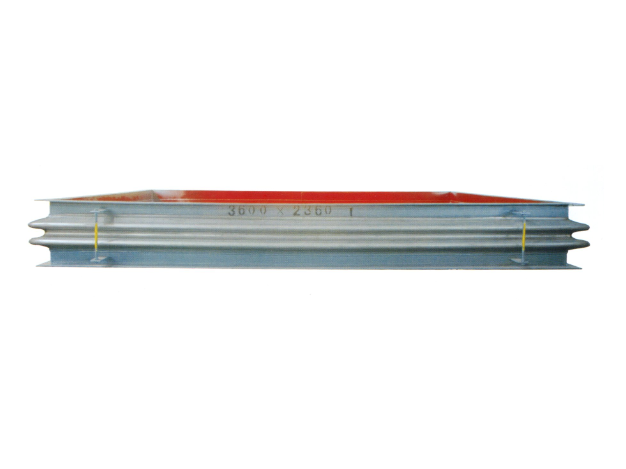
Metal rectangular expansion joint
Product introduction of metal rectangular expansion jointProduct Structure and C...
Learn more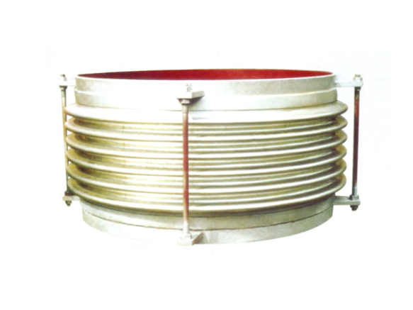
Universal corrugated expansion joint
The universal corrugated expansion joint is a kind of flexible compensation elem...
Learn more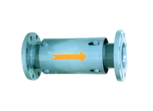
Single axial expansion joint
I. Structural compositionThe single axial expansion joint is mainly composed of ...
Learn moreCompensator, baffle door equipment · One-stop service process
From consultation to installation, we offer a full range of professional services
Consultation needs
The professional team will provide you with detailed product consultation and technical support to understand your specific needs
Scheme design
Provide personalized product design according to your specific needs to ensure the best solution
Manufacturing
Adopt advanced production equipment and technology and strict quality control to ensure excellent product quality
Installation and commissioning
Professional technicians provide on-site installation and commissioning services to ensure the normal operation of the equipment
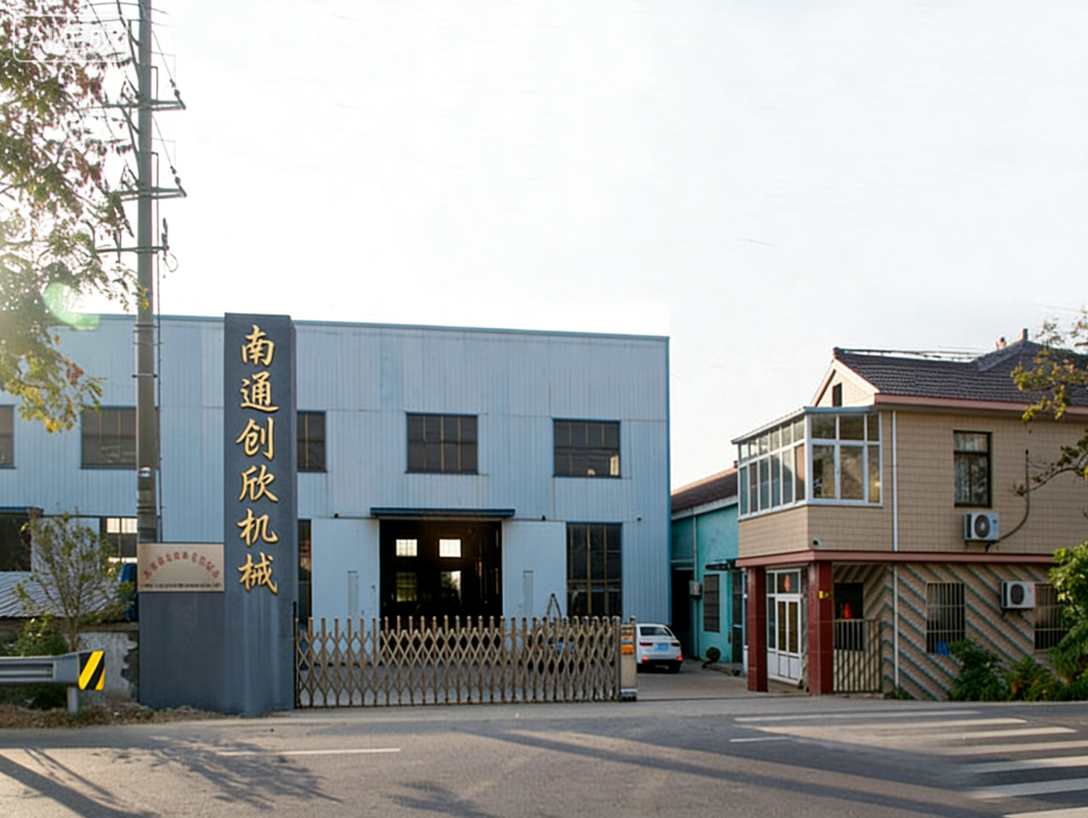
About Us
Nantong Chuangxin Machinery Co., Ltd. is located in the plain of central Suzhou, close to Nantong and Ningjingyan Expressway with convenient transportation, and less than 2 hours drive from Shanghai, Suzhou, Wuxi, Nanjing and other large and medium-sized cities.
The company is a comprehensive scientific and technological enterprise integrating design and development, production, product sales, installation and debugging. The company has successively communicated and cooperated with the National Cement Research Institute and the general contractor!
The company's main products are metal compensator (expansion joint), non-metal compensator (expansion joint), baffle door and other series products, providing excellent and cheap complete sets of equipment for the majority of users at home and abroad.
NEWS
Stay up-to-date with company and industry updates
Flue Expansion Joint Assembly and Connection: A Complete Guide for Site Construction
1. Importance of assembly and connection of flue expansion jointIn the...
Complete Analysis on Type Selection and Maintenance of Flue Expansion Joint of Electrostatic Precipitator in Power Plant
First, the core position of electrostatic precipitator flue expansion ...
Pressure plugging technology of flue expansion joint: a rapid repair scheme for non-stop furnace
1. Importance of pressure plugging of flue expansion jointIn continuou...
Application of flue expansion joint of desulfurization tower: from compensating displacement to ensuring environmental protection
1. Flue expansion joint of desulfurization tower: indispensable flexib...
Selecting the right flue expansion joint of gas turbine boiler inlet to make the unit safer
1. Choosing the right expansion joint: the first line of defense for s...
Pre-tension value of flue expansion joint: calculation method and setting standard
In the installation of flue system, the pre-stretching (also called pr...
Frequently asked questions
Answers to your frequently asked questions about compensators and baffle doors
1. Discussion on the Necessity of High Temperature Flue Expansion Joint
In the design of high-temperature flue systems such as industrial furnaces, boilers and roasters, a frequently asked question is: Does the high-temperature flue need to be equipped with expansion joints? The answer: must be set in the vast majority of cases. During the operation of high-temperature flue, as the temperature rises from normal temperature to hundreds or even thousands of degrees Celsius, the flue material will undergo significant thermal expansion. If the flue is a rigid continuous structure and no expansion joint is set to absorb thermal elongation, the huge thermal stress will lead to flue weld cracking, bracket failure, flange leakage and even overall flue instability deformation. However, whether each high-temperature flue must be provided with expansion joints, how many to set them, and what type to adopt need to be comprehensively judged according to the pipe length, working temperature, direction layout and bracket form. This paper will systematically answer this question from the calculation of thermal expansion, the feasibility evaluation of no expansion joint to the selection of setting scheme.
Calculation of thermal expansion: the basis for judging whether an expansion joint is needed
2.1 Basic Formula of Thermal Expansion
Answer high-temperature flue need to set expansion joint, first of all, calculate the thermal expansion of the flue. The calculation formula is as follows:
Δ L = α × L × (T_WORK-T_INST)
Among them:
- Δ L: thermal elongation (mm)
- α: Coefficient of linear expansion of material (/℃)
- L: Calculate the length of the pipe section (m)
- T_work: Operating temperature (℃)
- T_inst: Installation or initial temperature (℃)
2.2 Thermal expansion coefficient of common materials in high temperature flue
| Materials | Linear expansion coefficient α (×10⁻⁶/℃) | Applicable temperature range |
|---|---|---|
| Carbon steel (Q235B/20#) | 11-13 | ≤450℃ |
| Low alloy steel (15CrMo) | 12-14 | ≤550℃ |
| Stainless steel (304/316L) | 16-18 | ≤750℃ |
| Heat resistant steel (310S) | 14-16 | ≤1000℃ |
2.3 Calculation Example
A section of carbon steel flue with a length of 20m is set, the working temperature is 450 DEG C and the installation temperature is 20 DEG C, then:
Δ L =12×10⁻⁶ ×20000× (450-20) =103.2mm
This means that a 20m-long flue, after warming up to 450°C, elongates by about 103mm – equivalent to a displacement of 10cm. If both ends of the flue are rigid and fixed, this displacement has nowhere to be released, which will inevitably produce huge internal stress. Therefore, in this case, the answer to whether the expansion joint needs to be set in the high-temperature flue is clear: it must be set.
2.4 The critical length of the expansion joint needs to be set
| Operating temperature (℃) | Critical length (m) | Description |
|---|---|---|
| ≤150 | 50-60 | Thermal displacement is small and can be compensated naturally by pipe flexibility |
| 150-300 | 30-40 | Recommended calculation validation, usually required to set |
| 300-500 | 20-25 | Expansion joints must be provided |
| 500-800 | 10-15 | Expansion joints must be provided |
| >800 | 5-10 | High strength expansion joint + thermal insulation |
3. Feasibility conditions of not setting expansion joints
Although the vast majority of high-temperature flues need to be provided with expansion joints, they may not be provided under certain conditions.
3.1 Natural Compensation (Flexible Pipe Design)
The flexibility of the pipe itself can absorb part of the thermal displacement when there are sufficiently long straight sections and elbows in the flue stroke. This is the most common alternative to high-temperature flues. Conditions for natural compensation include:
- The flue is arranged in an L-, Z-or U-shape, with elbows providing flexibility
- The length of the pipe between the two fixed points does not exceed the critical value (see table above)
- The pipe wall thickness is thin (≤6mm) and the stiffness is low
3.2 Short-distance straight pipe sections
For straight pipe sections of very short length (e.g. length ≤3-5m from the outlet of the equipment to the first turn), the amount of thermal elongation is very small (usually ≤10mm), which can be absorbed by the clearance of the connecting flange, the flexibility of the equipment interface or the elastic deformation of the pipe. At this time, no expansion joint can be provided.
Typical example: The connecting section from the roaster outlet to the settling chamber is usually only 2-4m long, and the working temperature is 800-900℃. It can adopt thick-walled tube + large flange structure, and the elasticity of flange bolts is used to absorb a small amount of heat displacement, without separate expansion joints.
3.3 Sliding bracket and elastic connection
For longer flues, if expansion joints are not provided, sliding brackets can be arranged throughout the length, allowing the flue to extend freely, with elastic connections at the ends (e.g. packing box seals). This scheme is commonly used in horizontal directly buried thermal pipes, but it is less used in high temperature flues because its sealing reliability is not as good as that of expansion joints.
4. Typical working conditions where expansion joints need to be set
The answer to whether the expansion joint needs to be set in the high-temperature flue under the following working conditions is yes:
4.1 Long-distance straight pipe sections
When the long straight section of the flue exceeds the critical length (see Section 2.4) and goes straight without turning, axial expansion joints must be provided. Common in:
- Connecting flue from boiler outlet to dust collector
- Straight section of annular flue of roaster
- Original flue at inlet of desulfurization tower
4.2 Connections between High Temperature Equipment
When both devices are fixed independently (such as gas turbine exhaust port and waste heat boiler inlet), there is no common basis between the two, and the relative thermal displacement difference is significant, expansion joints must be set. Typical operating conditions:
- Gas turbine boiler inlet flue: the gas turbine exhaust temperature is 500-650℃, the boiler inlet is about 120℃, and the displacement difference is 30-60mm
- Connecting flue between roaster and cooler
4.3 Where the pipeline changes direction
When the flue changes direction at the elbow, thermal expansion causes lateral displacement of the elbow, creating lateral thrust on adjacent equipment. At this time, hinge type or universal expansion joints should be set on both sides of the elbow.
4.4 Where the flue passes through the wall or floor
When a flue crosses a building structure, wall or floor constraints will limit the axial displacement of the flue, and expansion joints must be provided on both sides of the crossing.
5. Risks and consequences of not setting expansion joints
If the operating conditions that should be set are not set, the following problems will arise:
| Risk | Specific performance | consequence |
|---|---|---|
| flue deformation | Local bulging, warping, flange surface warping | Compromised aesthetics, failed connection |
| Weld cracking | Thermal stress exceeds weld strength and cracks appear | Flue gas leakage, environmental protection exceeds standard |
| Stent failure | The fixing bracket is bent or pulled off | Loss of support, sinking or displacement of pipeline |
| Flange leakage | Gasket failure caused by warping of flange surface | Seal failure, need to stop the furnace |
| Device interface is damaged | The expansion force is transmitted to the device interface | Equipment shell cracked, high maintenance cost |
6. Suggestions on the selection of high-temperature flue expansion joint
6.1 Select Material by Temperature
After confirming whether the expansion joint needs to be set in the high-temperature flue and deciding to set it, the material of the bellows should be selected according to the flue temperature:
| Flue temperature (℃) | Recommended Bellows Material | Description |
|---|---|---|
| ≤450 | 304 stainless steel | Economical type, suitable for general boiler flue |
| 450-600 | 321 or 316L stainless steel | Titanium-containing stabilization, anti-sensitization |
| 600-800 | 309S or 310S stainless steel | Excellent high temperature oxidation resistance |
| 800-1000 | Inconel 625 | Nickel-based alloy, suitable for roasting furnace outlet |
| >1000 | Ceramic fiber + air-cooled structure | Metal expansion joints cannot be directly touched |
6.2 Selecting Structure by Displacement Direction
| Displacement characteristics | Recommended expansion joint types |
|---|---|
| Mainly axial displacement | Axial type or double axial type |
| Axial + transverse combination | Large tie rod transverse type |
| Angular displacement | Hinge type or universal hinge type |
| Multi-directional small displacement | Non-metallic fabric compensator |
6.3 Special configuration of high temperature expansion joint
For high temperature flues (≥600℃), the expansion joint requires the following special configuration:
- Guide tube: Prevent high-temperature smoke from directly washing the inner wall of the bellows
- Insulation layer: filled with ceramic fibers to reduce the temperature of the outer wall
- Multi-layer bellows: Reduce single-layer stress and disperse heat load
- Air-cooled or water-cooled structure: External cooling is required under extreme high temperature conditions
VII. Example in which the expansion joint is not required
To give a more comprehensive answer to whether an expansion joint needs to be set in a high-temperature flue, the following example does not need to be set:
- Short-distance connection section: the distance from the outlet of the equipment to the first fixed point is ≤3m, the working temperature is 500℃, the thermal elongation is ≤12mm, and can be absorbed by the elasticity of the pipeline
- Fully suspended flexible flue: The flue is suspended by a hanger, and the full length can swing and telescope freely
- Masonry flue with expansion joints: lined with refractory bricks, with expansion gaps reserved in the brick joints, thermal expansion absorbed by the brick joints, and the metal shell separated in sections
- Small-diameter pipes with bellows compensator as connectors: such as instrument pipes, sampling pipes and other pipes with diameter ≤100mm
VIII. Summary
The core judgment basis of whether the expansion joint needs to be set in the high-temperature flue is whether the thermal expansion amount of the flue exceeds the bearing capacity of itself and the support. When the amount of thermal elongation exceeds 10 mm or the length of the pipe section exceeds a critical value (20-30 m, depending on the temperature), setting the expansion joint is a necessary and economical solution; For the flue with short distance (≤5m), natural compensation elbow or flexible suspension structure, it may not be set.
After deciding to set the expansion joint, the bellows material should be selected according to the working temperature (321/316L is recommended above 450℃, 310S or Inconel is recommended above 600℃), and the expansion joint structure (axial type, large tie rod type or hinge type) should be selected according to the displacement direction. For the high-temperature flue above 600℃, it is necessary to configure a guide tube, heat insulation layer and multi-layer bellows.
It needs to be emphasized that the pipeline stress damage caused by blindly omitting the expansion joint often appears after a period of operation-it may take months or even years for the crack to expand from microscopic to macroscopic leakage, but once it happens, the repair cost far exceeds the investment of the original configuration of the expansion joint. Therefore, in the design, the calculation results of thermal expansion should be used as the basis, and the scientific decision should be made whether the expansion joint should be set in the high-temperature flue, so as to avoid the long-term potential safety hazard due to saving initial investment.
1. Importance of calculation of expansion joint stent
In pipeline systems, expansion joints are used to absorb thermal displacement and reduce stress, but they themselves cannot withstand internal pressure thrust and pipeline weight. If the bracket is set up incorrectly or calculated incorrectly, the expansion joint cannot compensate properly at least, and the pipeline system will be instable, the bracket will be damaged or even the bellows will be torn at worst. Therefore, the calculation of expansion joint support is a key step after pipeline design and expansion joint selection. Many engineers and technicians either ignore the internal pressure thrust or confuse the force difference between the fixed bracket and the guide bracket when calculating, resulting in serious safety hazards in the design documents. The core of stent calculation is to accurately determine the thrust generated by the expansion joint and rationally distribute it to the fixed stent, guide stent and intermediate stent. This paper will systematically expound the calculation methods of different types of brackets from force analysis, calculation formulas to engineering examples.
2. Types and functions of expansion joint brackets
2.1 Fixed bracket
To understand the calculation of expansion joint stent, first of all, the role of fixed stent should be clarified. A fixing bracket is a rigid structure that completely fixes the pipe and does not allow the pipe to displace or rotate in any direction. In pipes fitted with expansion joints, the fixed brackets bear the following loads:
- Internal pressure thrust generated by expansion joint (blind plate force)
- The frictional or elastic force caused by the thermal expansion of a pipe
- Elastic reaction force generated by bellows stiffness
- Dead weight of pipeline and medium weight
- Wind load, snow load (outdoor pipeline) and earthquake load
Fixed brackets are typically provided at both ends of the expansion joint, at the branch pipe, or where the pipe changes direction.
2.2 Guide Bracket
The guide bracket allows the pipe to move freely in the axial direction, but limits lateral and angular displacement. In the calculation of the expansion joint bracket, the calculation of the guide bracket is essentially different from that of the fixed bracket-the guide bracket does not bear internal pressure thrust, but only bears:
- Vertical load caused by pipeline dead weight
- Axial friction generated by thermal expansion of pipe
- Lateral constraints required to prevent instability
The spacing of the guide brackets is directly related to the stability of the pipeline under the action of compressive force, and excessive spacing will lead to buckling of the pipeline.
2.3 Intermediate bracket (ordinary bracket and hanger)
The intermediate support only bears the pipe's dead weight and vertical load, and does not limit the axial thermal displacement of the pipe. The calculation is relatively simple, and the conventional support and hanger design can be carried out according to the pipeline span and weight.
3. Force calculation of fixed bracket
3.1 Internal pressure thrust (blind plate force)
To answer the core question of the calculation of expansion joint bracket, the calculation of internal pressure thrust is the first task in the design of fixed bracket. Its calculation formula is:
F_p = P × A_eff
Among them:
- F_p: internal pressure thrust (N)
- P: working pressure (Pa)
- A_eff: Effective area of expansion joint (m²)
The effective area A_eff is not a simple internal cross-sectional area of the pipe, but the equivalent area of the bellows that generates thrust under pressure. For standard waveforms, the effective area is usually between the inner and outer cross-sectional areas, which can be approximated as follows:
A_eff = (π/4) × D_m²
Where D_m is the average diameter of the bellows (the average value of the crest diameter and the trough diameter).
Example of calculation:
Assuming that the inner diameter of the pipe is DN500, the average diameter of the bellows is D_m =550mm, and the working pressure is P =0.6MPa, then:
A_eff = π/4×0.55² =0.2376 m²
F_p =0.6×10⁶ ×0.2376=142,560 N ≈ 14.5 tonne force
This means that the internal pressure thrust generated by this expansion joint is up to 14.5 tons, which must be borne by the fixed brackets on both sides.
3.2 Elastic reaction force generated by bellows stiffness
When thermal displacement occurs in the pipe, the expansion joint bellows can be compressed or stretched, creating an elastic reaction force:
F_s = K × Δ L
Among them:
- K: axial stiffness of expansion joint (N/mm)
- Δ L: Actual displacement (mm)
3.3 Pipe Friction and Weight
Friction when the pipe moves on the guide bracket:
F_f = μ × W × L
Among them:
- μ: friction coefficient (0.3 for steel-to-steel sliding and 0.1 for rolling bracket)
- W: Weight of pipe and media per unit length (N/m)
- L: length of pipe from expansion joint to fixed bracket (m)
3.4 Total load of fixed bracket
The final result of the calculation of the expansion joint bracket-the total load of the fixed bracket is the vector sum of the respective partial loads. In the axial arrangement, the loads on both sides of the fixed bracket are in opposite directions, and the total load is the difference between the loads on both sides (take the greater value).
When there are pipes on both sides of the expansion joint, the total axial force on the fixed bracket is:
F_total = max (F_left, F_right) -min (F_left, F_right) The absolute value of, plus the algebraic sum of the co-directional loads on both sides.
4. Arrangement and spacing calculation of guide brackets
4.1 Functional positioning of guide bracket
In the calculation system of the expansion joint bracket, the guide bracket does not bear the internal pressure thrust, and its core functions are:
- Ensure that the expansion joint moves along the axis direction and does not bend laterally
- Prevent column instability of bellows under pressure
- Limit the lateral displacement of the pipe to the specified range
4.2 Determination of spacing between guide brackets
The maximum spacing of the guide brackets is related to the pipe diameter and the rigidity of the bellows. Experience Recommended by EJMA Standards:
| Nominal diameter DN (mm) | Maximum spacing between guide brackets (m) |
|---|---|
| ≤150 | 4 |
| 200-350 | 6 |
| 400-600 | 8 |
| 700-1000 | 10 |
| >1000 | 12 |
The distance between the first guide bracket and the expansion joint port shall not exceed 4 times the nominal diameter of the expansion joint and not exceed 4m.
4.3 Forces on guide brackets
The guide bracket mainly bears the vertical load of the pipeline's own weight and the friction force during axial movement, but does not bear the internal pressure thrust. Its vertical load is calculated by weight distribution within the pipe span.
Note: There should be a gap (usually 2-5mm) between the guide surface of the guide bracket and the pipe to avoid sticking and causing the expansion joint to be unable to expand and contract freely.
5. Calculation characteristics of bracket with tie rod expansion joint
5.1 Function of the tie rod
For expansion joints with large tie rods (such as large tie rod transverse type, hinge type, etc.), the tie rod directly bears internal pressure thrust and is not transmitted to the fixed bracket. This is an important change in the calculation of the expansion joint bracket-the fixed bracket only needs to withstand the elastic reaction force and pipe friction generated by the rigidity of the bellows, and the load is significantly reduced.
5.2 Forces on the fixed brackets on both sides of the tie rod expansion joint
When the expansion joint is set with a tie rod:
F_fixed = F_s + F_f
Where F_p has been internally balanced by the tie rod and no longer acts on the pipe support.
This characteristic makes the tie rod expansion joint particularly suitable for retrofit projects where fixed brackets are difficult to set or carrying capacity is insufficient.
VI. Actual engineering calculation steps
6.1 Collection of underlying data
Before performing the expansion joint stent calculation, the following data need to be prepared:
- Pipe diameter, wall thickness, material
- Operating pressure, operating temperature, installation temperature
- Expansion joint model, effective area, axial stiffness
- Pipe layout drawing, pipe rack position
- Pipes and media weight, insulation weight
6.2 Calculate the total displacement of the expansion joint
Δ L_total = α × L × (T_work-T_inst)
Among them:
- α: Linear expansion coefficient (carbon steel about 12×10⁻⁶/℃)
- L: length of pipe between two fixed brackets (m)
- T_work, T_inst: Operating temperature, installation temperature (℃)
6.3 Calculate the total load of fixed bracket
According to the formula in Section 3, calculate the internal pressure thrust, elastic reaction force, and friction force item by item, and then sum them.
6.4 Check the strength of the stent
The calculated load is taken as the design input, and the strength of the steel structure, anchor bolts and foundation of the fixed bracket is checked. The safety factor is generally 1.5-2.0.
Common Calculation Errors and Correction
| Error Type | Error performance | Correct practice |
|---|---|---|
| Effective area misuse | Replacing the effective area with the internal cross-sectional area of the pipe | Calculation of effective area using mean diameter of bellows |
| Ignore internal pressure thrust | Only the elastic force due to thermal displacement is calculated | Must account for internal pressure thrust (no tie rod expansion joint) |
| Guide bracket receives thrust | Design the guide bracket according to the fixed bracket | The guide bracket only guides and is not fixed |
| Improper value of friction coefficient | Take 0.3 uniformly | Value according to bracket type (rolling bracket 0.1) |
| Safety factor not considered | Direct use of calculated values | Safety factor of 1.5-2.0 for bracket design |
VIII. Calculation Examples
Working condition: DN600 steam pipeline, P =0.8MPa, T_work =250℃, installation temperature 20℃, distance between two fixed brackets 30m. An axial expansion joint with effective area of 0.32m² and axial stiffness K =2000N/mm was selected. Friction coefficient μ =0.3, unit weight of pipe and medium is 1200N/m.
Thermal displacement: Δ L =12×10⁻⁶ ×30× (250-20) =0.0828m =82.8mm
Internal pressure thrust : F_p =0.8 x 10⁶ x 0.32=256,000 N
Elastic reaction force : F_s =2000×82.8=165,600 N
frictional force : F_f =0.3×1200×30=10,800 N
total load of fixed bracket: F_total = F_p + F_s + F_f =256,000+165,600+10,800=432,400 N ≈ 44 tonnes force
The fixed bracket should be structurally designed according to the axial thrust of 44 tons, and the safety factor should be 1.5 times.
IX. SUMMARY
The calculation of expansion joint support is a fundamental and critical task in pipeline stress analysis. The core can be summarized as follows: "The internal pressure thrust depends on the effective area, the stiffness reaction force depends on the displacement, the fixed bracket carries the sum, and the tie rod structure can be self-balanced".
In the calculation process, the different functions of the fixed bracket and the guide bracket must be clearly distinguished: the fixed bracket bears the sum of internal pressure thrust, elastic reaction force and friction force, among which the internal pressure thrust often accounts for the largest proportion, which can not be ignored by calculating the effective area formula F_p = P × A_eff; The guide bracket only bears the vertical load and friction of self-weight, and does not bear the internal pressure thrust. The spacing of the guide bracket should be controlled within the specification range to prevent pipe buckling. For expansion joints with tie rods, the internal pressure thrust is self-balanced by the tie rods, and the fixed bracket load is significantly reduced.
In the specific operation, the data of pipeline parameters, working conditions and expansion joint characteristics should be collected first, and the thermal displacement, internal pressure thrust, elastic reaction force and friction force should be calculated in turn. Finally, the safety factor of 1.5-2.0 should be summed and considered. Common mistakes include replacing the effective area with the internal cross-sectional area of the pipe, ignoring the internal pressure thrust, and confusing the functional positioning of the fixed bracket with the guide bracket. Through the correct calculation and design of the expansion joint bracket, the expansion joint can play a safe and reliable compensation role in the pipeline system, and avoid pipeline deformation, expansion joint damage and even safety accidents caused by the failure of the bracket.
1. Harm and Urgency of Boiler Flue Expansion Joint Leakage
In power station boiler and industrial boiler system, flue expansion joint takes on the important functions of absorbing heat displacement, absorbing shock and noise and sealing flue gas. However, long-term exposure to high temperature, corrosive media and alternating stress environment, the expansion joint will inevitably have leakage problems. Whether the leakage treatment of boiler flue expansion joint is timely and appropriate is directly related to the operating efficiency of boiler, environmental protection emission index and the safety of on-site personnel. Flue gas leakage not only leads to the increase of energy consumption of induced draft fans and the aggravation of local flue corrosion, but also may lead to fines for exceeding environmental protection standards. More seriously, high-temperature smoke (up to 150-400℃) leaks to the surrounding areas, resulting in scald risks and fire hazards. Therefore, establishing a set of scientific and rapid leakage treatment scheme is the core skill that boiler operation and maintenance personnel must master. This article will systematically introduce the complete treatment process from leak type diagnosis, temporary plugging to permanent repair.
2. Type and cause diagnosis of boiler flue expansion joint leakage
2.1 Classification by leak location
Before carrying out boiler flue expansion joint leak treatment, it is first necessary to accurately locate the leak location. Common leak sites include:
| Leakage location | Typical characteristics | Common causes |
|---|---|---|
| Bellows body | Pinhole spray, multiple leakage | Pitting, stress corrosion, fatigue cracking |
| Weld (Bellows-Flanges/Connections) | Linear leakage along weld | Welding defects, thermal fatigue, dissimilar steel welding failure |
| Flange connecting surface | Leakage at the gasket and soot around the bolt | Gasket aging, bolt loosening, flange surface deformation |
| Connection between the guide tube and the housing | Internal leak, possibly leaking out of insulation | Guide tube fixed weld cracked |
2.2 Classification by leakage mechanism
Leakage caused by different mechanisms, boiler flue expansion joint leakage treatment methods are also completely different:
- Corrosion leakage: The flue gas contains SO₂, SO₃, Cl⁻¹ and other corrosive media, which forms acidic corrosion under the action of condensate, and the wall thickness of bellows gradually decreases to perforation. It is more common in the expansion joint at the inlet or low temperature section of desulfurization system.
- Fatigue leakage: Under the action of repeated thermal displacement, fine cracks appear at the crest or trough of the bellows, which gradually expand into penetrating cracks. It is common in peak shaving units with frequent start-and-stop.
- Overload leakage: The expansion joint is subjected to displacement beyond the design value due to bracket failure or installation pre-displacement error, resulting in local tearing of the bellows.
- Scour leakage: the guide tube falls off or the guide tube is not set, and the dusty flue gas directly washes the inner wall of the bellows, resulting in abrasion and perforation.
2.3 Methods for rapid diagnosis of leaks
The following methods can be used to quickly locate the leakage point on site:
- Visual inspection: Observe soot traces after shutdown. There is usually white or black soot accumulation around the leakage point
- Soap water leak detection: Spray soap water on the suspected leakage part, and continuous air bubbles can be seen under positive pressure
- Smoke generator: The negative pressure flue can release smoke near the expansion joint, and observe whether the smoke is inhaled
- Infrared thermal imaging: the temperature at the leakage is abnormal, and there are obvious hot or cold spots on the thermal image (positive pressure leakage is a hot spot, and negative pressure leakage of cold air is a cold spot)
3. Temporary treatment measures for boiler flue expansion joint leakage
When a leak is found and the boiler cannot be shut down immediately, the following temporary measures can be taken to control the leak and buy time for the planned shutdown.
3.1 Leak plugging under pressure (positive pressure flue)
For the leakage treatment of boiler flue expansion joint in positive pressure flue, pressure plugging is the most commonly used temporary scheme:
- Small hole leakage (≤3mm): Use tapered wooden plug or metal tapered plug to knock into the leakage hole, and apply high temperature sealant (temperature resistance ≥300℃) on the outside
- Crack leakage: Drill crack stop holes (φ 3-5mm) at both ends of the crack, and then tie them with clamps or steel strips, lined with high temperature resistant gaskets
- Flange leakage: Use flange pressure plugging fixture, inject high temperature sealing injection, or add clamp on the outside
It should be noted that pressure plugging is only used as a temporary emergency measure and should not replace permanent repair.
3.2 Outer Wrap Sealing
For large area leaks that cannot be plugged at a single point:
- High temperature resistant stainless steel sheet (thickness 0.5-1.0mm) is cut into wrapping shape
- Lined with ceramic fiber blanket or high temperature sealing gasket
- Tie and fix on the outside of the expansion joint with stainless steel belt or wire rope
- Apply high-temperature sealant to the interface
This method can significantly reduce the amount of leakage without stopping the furnace, and is suitable for short-term transitions before planned maintenance (generally no more than 1 month).
3.3 Temporary treatment of negative pressure flue
For negative pressure flue, the leakage is manifested by external cold air being sucked in. Although there is no risk of smoke leakage, it will affect the accuracy of smoke monitoring data and increase the load of induced draft fan. Provisional processing may be adopted:
- Apply high temperature resistant aluminum foil tape to the outside of the leak
- Apply high temperature repair mud
- In severe cases, it can be covered with a sealing cloth and vacuum attached
IV. Permanent leakage repair after boiler shutdown
4.1 Local repair welding
For corrosion pits or small-scale cracks, repair welding can be used to repair them. Repair welding in boiler flue expansion joint leakage treatment should strictly follow the following process:
- Clean-up: Thoroughly remove oil, rust and soot around the leakage point and polish to the natural color of metal
- Groove preparation: the crack is polished and grooved, the groove is deep to the bottom of the crack, and the angle is 60-70°
- Welding method: Tungsten Arc Welding (TIG), low current, fast welding
- Welding material selection: Match with base metal, stainless steel expansion joint with the same material welding wire; Transition welding material for dissimilar steel parts
- Post-weld treatment: polishing the weld residual height and performing 100% penetration test
IMPORTANT NOTE: The thickness of corrugated pipe substrate is usually only 1-3mm, which is easy to burn through or cause thermal deformation during repair welding. It is recommended to be operated by welders with thin plate welding qualifications, and the length of single continuous welding does not exceed 10mm, segmental jump welding.
4.2 Local replacement of bellows
When the leakage area is large (greater than 50cm²) or multiple leakage points are concentrated, local repair welding is no longer reliable, and local replacement of bellows should be performed:
- Remove the corrugated pipe from the damaged section, leaving both ends intact
- Prepare a new corrugated pipe section (the wave shape and material should be consistent with the original)
- Butt joint welding was used, and the weld seam was 100% radiographic inspection
- The compensation ability and stiffness of the expansion joint should be re-checked after replacement
4.3 Overall replacement of expansion joints
It is recommended to directly replace the expansion joint in its entirety instead of repairing it locally in the following cases:
- Multiple fatigue cracks in the bellows, approaching the design fatigue life (usually 1000 cycles)
- Improper material selection (if the original 304 is used, the actual need is 316L)
- The guide tube falls off and causes extensive wear of the bellows
- Structural defects of expansion joints (such as wave height and wave pitch not meeting the standard)
When replacing the whole, it is necessary to install in place, butt welding and limit adjustment according to the original design requirements.
V. Liner repair and seal strengthening
5.1 Liner Inspection and Repair
In the treatment of boiler flue expansion joint leakage, lining damage is often the cause of leakage. The repair steps are as follows:
- Check the guide tube for detachment, deformation and wear
- Check the heat insulation layer (ceramic fiber blanket) for burn and collapse
- To repair local damage: fill in ceramic fiber cotton and apply high-temperature cement to the surface
- If the guide tube falls off, it should be re-welded and fixed, and segment welding should be used to prevent deformation during welding
5.2 Flange Seal Replacement
For flanged connection structure leakage:
- Remove all bolts, clean up old gaskets and corrosion on flange surface
- Check the flatness of the flange surface and smooth the local high points with a grinder
- Select a suitable new gasket: Stainless steel clad graphite pad or high strength graphite composite pad is recommended
- Tighten the bolts 2-3 times in cross-symmetric order to achieve the specified torque
- After tightening, check that the flange clearance is uniform and the deviation is ≤0.3mm
Maintenance strategies to prevent leakage
6.1 Regular inspection system
The establishment of a regular inspection system for expansion joints can greatly reduce the risk of sudden leakage:
- Monthly: Visually check for soot traces and discoloration of the insulation layer
- Quarterly: Infrared thermography examination to compare temperature distribution for abnormalities
- Semi-annually: Internal inspection at shutdown to measure bellows wall thickness (ultrasonic thickness measurement)
- Annually: Check the integrity of deflectors, anchors, lining materials
6.2 Leak warning indicators
Incorporate the following indicators into the boiler operation monitoring system for early warning:
- Induced draft fan current is abnormally increased (flue leakage increases air volume demand)
- Abnormal flue oxygen (high oxygen due to negative pressure leakage and inhaled air)
- Sudden change in surface temperature of expansion joint (abnormal temperature near leakage point)
6.3 Life Management Ledger
Establish a full lifecycle profile for each expansion joint:
- Date of commissioning, design fatigue life
- Time and frequency of each start-and-stop
- Record of previous leaks and repairs
- Analysis of the trend of wall thickness thinning
When the cumulative number of cycles reaches 80% of the design life, it is included in the scheduled replacement list.
VII. Common problems and countermeasures
| Question | Probable cause | Treatment countermeasures |
|---|---|---|
| Again leakage in a short period after repair welding | Corrosion acceleration in heat-affected zone of repair welding area | Use that same material of welding material, pickling and passivation after welding |
| Multiple simultaneous leakage | Overall fatigue life exhaustion | No more patching, whole replacement |
| Still leaking after flange face repair | Severe deformation or warpage of flange surface | On-site machining to repair the flange surface or replace the flange |
| Leak found in insulation | The internal weld cracks, and the flue gas bursts into the interlayer | Remove insulation, check internal welds and repair welds |
VIII. Summary
Boiler flue expansion joint leak treatment is a systematic work from rapid diagnosis to standard repair. The key to successfully handling leaks can be summarized as follows: "locate first, classify, plug if urgent, fill if slow, and replace if serious". For the leakage occurring in operation, first of all, the leakage location and mechanism must be accurately judged. Positive pressure flue can be temporarily controlled by pressure plugging, but it must not be relied on for a long time; After the planned furnace shutdown, repair welding, local replacement or overall replacement schemes should be selected according to the damage degree of the bellows, and the lining, guide tube and flange seal should be repaired simultaneously. In the long run, it is more economical and effective to establish a regular inspection system, life management ledger and leak warning indicators than passively handling leaks. For the boiler flue with frequent leakage, it is recommended to fundamentally review whether the expansion joint selection is reasonable, whether the bracket is set correctly, and whether the operating conditions are beyond the design range. Through standardized leakage treatment and perfect preventive measures, the risk of unplanned shutdown caused by expansion joint leakage can be minimized, and the safe, environmental protection and economic operation of boiler system can be ensured.
1. Necessity and difficulty of replacing metal expansion joint in flue of power plant
In power plant boiler and desulfurization and denitrification system, the metal expansion joint has been subjected to the joint action of high temperature flue gas erosion, alternating thermal stress and corrosive medium for a long time, and gradually problems such as bellows cracking, guide tube falling off and seal failure appear. When the leakage exceeds the standard or the structural damage affects the safe operation, it is necessary to face the practical problem of how to replace the metal expansion joint in the flue of power plant. Compared with new installation construction, replacement operation is often limited by various unfavorable factors such as shutdown time window, limited space, deformation of old structure, etc., which puts forward higher requirements for construction scheme and on-site operation.
Preparation before replacement: from furnace shutdown conditions to technical data
2.1 Furnace shutdown conditions and safety isolation
To answer how to replace the metal expansion joint of the flue of the power plant, first of all, the safety premise should be clarified. The flue where the expansion joint to be replaced is located must be randomly shut down, and the following isolation measures must be completed:
- Cool to below 50℃: Forced ventilation or natural cooling to prevent scalding and thermal deformation
- Media cut-off: Close baffle door, plug-in valve, and install blind plate if necessary
- Gas replacement: The flue gas system shall be subjected to air replacement, and the oxygen content and toxic and harmful gases (CO, SO₂, etc.) shall be detected
- Lock and tag: execute energy isolation procedure, prohibit misoperation
2.2 Site Mapping and Condition Assessment of Old Expansion Joints
Due to long-term high-temperature operation, the original installation dimensions may have changed, and it is strictly prohibited to purchase replacement parts directly based on as-built drawings. On-site measurements shall be made:
- Actual spacing of flue flanges or interfaces (3 measuring points each upstream and downstream)
- Axial and transverse offset of bellows
- Connection mode (flanged, direct welded or plug-in)
- Wear and dust accumulation of guide tube
According to the measured data, determine the length, wavenumber and interface size of the replacement parts to ensure "new and old".
2.3 Replacement Plan Preparation and Acceptance Criteria
Before replacement, a construction plan shall be formulated, including at least: dismantling and hoisting methods, welding process requirements, counterpart accuracy standards, non-destructive testing proportions, pressure and leakage test plans. The acceptance criteria are usually DL/T 1121 Technical Specifications for Metal Expansion Joints for Flue Gas Dust Removal of Boilers in Coal-fired Power Plants or GB/T 12777.
3. Demolition operation: How to safely and completely remove the old expansion joint
3.1 Sequence of removal of expansion joint
Demolition is the key first step to answer how to replace the flue metal expansion joint of a power plant. It is recommended to operate in the following order:
- Cleaning up dust accumulation: Remove dust accumulation at the bottom of wave trough, guide tube and flue to reduce hoisting weight
- Release Tie Rod/Limit Device: Record factory pre-tension or cold tightening position, loosen nut or remove tie rod
- Cutting welds or removing flanges: If it is a welded structure, leave 5-10mm margin for cutting along the flue side to avoid damage to the main flue base metal
- Sectional disassembly: For large-size rectangular expansion joints, one-sided corrugated components can be disassembled first and hoisted out in blocks
- Groove trimming: Remove residual welds and reprepare grooves according to welding process
3.2 Cutting Method and Flue Protection
It is recommended to use plasma cutting or mechanical cutting, and use gas cutting with caution (large heat influence and easy splash). When cutting, adjacent equipment and cables are shielded from fire, and fire extinguishing equipment is equipped in the flue.
3.3 Hoisting and temporary support
Immediately after the old expansion joint is removed, temporary supports or temporary blind plates shall be set on the disconnected surface of the flue to prevent the pipe from sinking or foreign objects falling into the system. Measure the staggered notch and non-parallelism of two sections simultaneously, as the adjustment basis of the new expansion joint in place.
4. Installation of new expansion joint: countermouth, welding and limit adjustment
4.1 Pipe Matching and Pre-Compression/Pre-Stretching
When installing a new metal expansion joint, it is necessary to determine whether pre-displacement is required according to the design displacement direction and the actual temperature at the time of installation:
- Installation at normal temperature (≤20℃): Pre-stretch or pre-compress according to the cold tightness given by the design institute
- Hot state (> 100℃) emergency repair installation: Calculate the thermal elongation corresponding to the actual shell temperature and adjust the installation length
Allowable deviation of counterpoint: axial deviation ≤3mm, radial misalignment ≤1.5mm (based on the thin-walled side), strong counterpoint is strictly prohibited.
4.2 Welding Process and Weld Quality
Welding shall be performed in accordance with the qualified WPS as assessed. For how to replace the metal expansion joint of the flue of the power plant, it is recommended that:
- Base layer: TIG welding to ensure root penetration and no oxidation on the back
- Filling and cover layer: SMAW or semi-automatic welding, strictly control the interlayer temperature ≤150℃
- Welding sequence: welding in segments symmetrically along the circumference to reduce shrinkage deformation
For different steel welding between austenitic stainless steel expansion joint and carbon steel flue, transition layer welding material (such as E309 series) should be selected, and small parameter and rapid welding process should be adopted to reduce hot crack and dilution rate.
4.3 Resetting of pull rod and limit device
After welding and cooling, reset tie rod nuts according to design requirements:
- Structure for transmitting thrust: The pull rod shall be in a stressed state, and the nut shall be properly tightened
- Structures for transportation protection only: The tie rod should be completely loosened or removed to avoid restricting the normal operation of the expansion joint
For structures with hinges or gimbal rings, confirm that the rotation is flexible and not stuck.
V. Inspection and acceptance: the key link to ensure the quality of replacement
5.1 Non-destructive testing of welds
- Surface test: 100% penetration test (PT) or magnetic particle test (MT) for all pressure-bearing or sealed welds, Class I qualified
- Internal inspection: Ray inspection (RT) for butt welds on a proportional basis, not less than Grade II
5.2 Tightness Test
The tightness test shall be carried out after the metal expansion joint is replaced. Common methods:
- Negative pressure flue: Start the induced draft fan to establish negative pressure, and use a candle or smoke generator to check the weld seam leakage
- Positive pressure flue: under the premise of safety and control, 0.05-0.1MPa compressed air pressure is maintained, and leak detection liquid is applied
5.3 Hot state review and operation monitoring
After the start-up of the unit, infrared thermal imaging and displacement observation of the expansion joint shall be carried out at 30%, 60% and 100% load stages:
- There is no abnormal overtemperature or local overheat on the bellows surface
- The actual displacement direction is consistent with the design
- No abnormal vibration or noise
VI. Frequently Asked Problems and Suggestions
| Question | Probable cause | Treatment measures |
|---|---|---|
| The new expansion joint does not fit | Flue rebound or sink after removal | Add temporary supports, pull and reset or replace with adjustable expansion joints |
| Bellows weld cracking | Wrong pre-displacement or tie rod not loose during installation | Recalculate the installation length and adjust the limit according to the actual working conditions |
| Leakage after replacement | Defective weld or damaged gasket | Local repair welding or replacement gasket (high temperature sealant + ceramic fiber) |
| Short replacement period ( | Excessive flue gas flow rate or thin type selection | Increase wall thickness or replace low-cycle fatigue bellows |
VII. SUMMARY
How to replace the metal expansion joint of the flue of the power plant is not a simple "dismantling the old and installing the new", but a set of systematic engineering including furnace shutdown isolation, surveying and mapping customization, cutting and dismantling, accurate matching, welding control and tightness verification. The key to successful replacement is to guide the manufacture of new parts by measured data, control the deformation by symmetrical welding, and ensure the seal by specification inspection. For power plant maintenance personnel, selecting a construction team with similar coal-fired or gas-fired unit replacement experience, operating in strict accordance with the welding process regulations, and allowing sufficient hot state review time after replacement can significantly reduce the risk of secondary leakage and the probability of non-shutdown of units. Through the standardized replacement operation, not only the sealing and compensation function of the flue system can be restored, but also the whole life cycle of the expansion joint can be prolonged, which provides reliable guarantee for the safe and stable operation of the unit.
In the flue gas treatment system of coal-fired power plant, chemical industry and metallurgy industry, flue expansion joint corrosion is a common problem that affects the safe operation of equipment and the environmental protection standard. Whether it is the cracking of the bellows of the metal expansion joint or the leakage of the skin of the non-metal expansion joint, the corrosion problem not only leads to flue gas leakage and pollutes the environment, but also increases the energy consumption of the fan and shortens the equipment life. So, what about flue expansion joint corrosion? This paper will start with the analysis of corrosion mechanism, systematically explain the corrosion causes, coping strategies and engineering practice cases of different types of expansion joints, and provide professional solutions for technicians.
1. Main types and causes of flue expansion joint corrosion
To answer "What to do about flue expansion joint corrosion", you first need to clarify the type and root cause of corrosion. According to the engineering failure analysis, the corrosion of flue expansion joint is mainly divided into the following categories:
1.1 Dew Point Corrosion
When the flue gas temperature is below the acid dew point, SO₂ and SO₃ in the flue gas will combine with water vapor to form dilute sulfuric acid, which condenses and deposits on the surface of the expansion joint. This condensate is strongly corrosive to carbon steel and ordinary stainless steel。
Typical characteristics: The corrosion is evenly distributed, mostly occurring at the fluid accumulation at the bottom of the expansion joint, showing honeycomb or pit erosion.
1.2 Stress Corrosion Cracking (SCC)
Stress corrosion is the most common cause of metal expansion joint bellows failure. While subjected to pressure and displacement stresses, corrugated pipes are exposed to corrosive media (sulfur-containing flue gas), which can crack under conditions well below the yield strength of the material。
Typical features: The crack is dendritically branched, originating from the inner surface of the bellows and propagating along the crystal. Failure analysis of Inconel 625 bellows in a catalytic cracking unit shows that the NiS eutectic (melting point only 645 ℃) formed at grain boundary is the key factor inducing stress corrosion。
1.3 Intergranular corrosion
Because the grain boundary of the welding heat affected zone or the material itself is chromium depleted, the grain boundary is preferentially eroded under the action of the corrosive medium, resulting in cracking of the bellows along the grain boundary。
1.4 Chemical Corrosion and Liquid Corrosion of Non-Metallic Expansion Joints
In the desulfurization flue, although the main material (fluororubber, PTFE) of the non-metallic expansion joint skin is corrosion-resistant, there are inherent defects in its fixation mode. Grooves will be formed at the connection between the skin and the flange, and condensed acid water will accumulate during operation. The acid water will gradually penetrate through the skin fabric layer and corrode the fixing bolts, resulting in bolt breakage and skin loosening and leakage。
2. Countermeasures of flue expansion joint corrosion
For different types of corrosion, what to do about flue expansion joint corrosion needs to take differentiated technical measures:
2.1 Anti-corrosion measures of metal expansion joints
(1) Material upgrade
| Operating condition | Recommended Material | Applicable temperature | Corrosion resistance characteristics |
|---|---|---|---|
| Conventional high temperature flue | 304 stainless steel | ≤600℃ | Generally antioxidant, not resistant to chloride ions |
| Sulfur-containing corrosion flue | 316L stainless steel | ≤650℃ | Added Mo, resistant to sulfide and chloride ions |
| Severe corrosion of flue | Inconel625 | ≤700℃ | Nickel-based alloy, resistant to oxidation and vulcanization at high temperatures |
Of particular interest is the application of pure titanium expansion joints. The practice of Huadian Luohe Power Plant proves that the 2mm thick TA2 pure titanium expansion joint is adopted in the desulfurization wet flue, and the surface is as clean as new after one year of continuous operation, thus achieving "zero corrosion and zero leakage". Because that density of titanium is low (4.5g/cm³), the weight of titanium is more than 40% lighter than that of stainless steel under the same size, and the total cost is basically the same as that of non-metallic expansion joint。
(2) Structural Optimization
In view of stress corrosion cracking, it is suggested that the expansion joint bellows be upgraded from a single-layer structure to a double-layer structure, and the concept of "single-layer pressure bearing and double-layer design" is adopted. The double-layer structure can cooperate with the interlayer leakage online monitoring system. Once the inner layer leaks, the outer layer plays a buffer and protection role, and at the same time sends out early warning signals to avoid unplanned shutdown caused by sudden failure。
(3) Operation and maintenance measures
- Furnace shutdown protection: During maintenance, hot air is used to purge the inside of the expansion joint to prevent the condensation and deposition of sulfur-containing gas
- Temperature control: Increase the exhaust temperature above the acid dew point to avoid the formation of condensate
- Regular replacement: Replace the bellows regularly according to the design life (usually 3-5 years) to avoid overdue service
2.2 Anti-corrosion measures of non-metallic expansion joints
(1) Skin material optimization
The skin of non-metallic expansion joint should adopt multi-layer composite structure, and the materials of each layer should be accurately selected and matched according to the working conditions:
| horizon | RECOMMENDED MATERIAL | function |
|---|---|---|
| Outer layer (weather resistant layer) | Fluorine rubber (FKM) | High temperature, corrosion and aging resistance |
| Intermediate layer | PTFE membrane + alkali-free glass fiber cloth | Chemical isolation, enhancement |
| inner layer | Fluorine rubber + stainless steel wire mesh | Corrosion and scour resistance |
For the desulfurization clean flue, the skin material should be fluororubber instead of silicone rubber. Fluororubber has extremely high resistance to acid and alkali and high temperature saturated wet smoke。
(2) Structural improvement-radical cure scheme for effusion problem
The root cause of leakage of non-metallic expansion joints is the accumulation of acid water in the grooves at the skin platens。 Solutions include:
- Drainage design: Add a drainage pipe above DN100 at the bottom of the expansion joint to discharge the condensate in time
- Anti-corrosion of flange end face: Laying glass flake anti-corrosion layer and glass fiber reinforced plastic anti-corrosion layer on steel substrate in sequence, and then installing rubber elastic expansion joint, and fill the layers with silica gel seal
- Bolt protection: The fixing bolts are made of 316L stainless steel, coated with anti-loosening glue during installation, and periodically tightened
(3) Installation process control
- When the skin is installed, it should be unfolded from bottom to top, and the pressure plate bolts should be tightened repeatedly for 2-3 times
- Horizontal flue expansion joint, the outermost skin interface shall adopt the "up-pressing-down" overlap mode to prevent rainwater infiltration
3. Overall replacement scheme: thoroughly solve frequent corrosion
For expansion joints with repeated leakage and low repair value, the whole replacement with expansion joints made of high performance materials can be considered.
Project case: The outlet expansion joint of induced draft fan of 2#boiler of a company has been eroded and washed by high-temperature flue gas for a long time, resulting in serious leakage. Through the accurate formulation of special maintenance plans, the removal of old expansion joints, installation of new corrosion-resistant expansion joints, seal inspection and other procedures were completed, and finally one-time debugging was successful. After the replacement, the corrosion loss of the equipment is significantly reduced, and the operating efficiency of the induced draft fan is greatly improved。
4. Suggestions on anti-corrosion selection of different types of flues
| Flue type | Characteristics of working conditions | Recommended expansion joint types | Key anti-corrosion measures |
|---|---|---|---|
| Boiler tail flue | 120-180℃, dusty | 316L Metal Expansion Joint | Inner lining guide tube anti-scour |
| Desulfurization raw flue | 120-150°C with SO₂ | Fluororubber non-metallic expansion joint | Skin multi-layer composite + bottom drainage |
| Clean flue for desulfurization | 45-80℃, saturated wet flue gas | Pure titanium expansion joint/fluororubber + TA2 composite | Titanium monolithic structure or TA2 skin |
| Catalytic cracking flue | 650-700℃, containing sulfur | Inconel625 Double Bellows | Material Upgrade + Interlayer Monitoring |
| bypass flue | Instantaneous high temperature, intermittent operation | High temperature resistant non-metallic expansion joint | Strengthening insulation |
V. Summary
Faced with the engineering problem of how to deal with the corrosion of flue expansion joint, the core lies in "prescribing the right medicine"-choosing the appropriate technical scheme according to the corrosion type and working conditions. Summary points are as follows:
- Identify corrosion types: dew point corrosion requires temperature control and condensation prevention; Stress corrosion requires material upgrading and stress relief; Intergranular corrosion needs to control the welding process and material selection.
- Material is the key: conventional desulfurization net flue recommends fluororubber non-metallic expansion joint.
- Anti-corrosion of metal bellows: Nickel-based alloys such as Inconel625 are selected for high-temperature sulfur-containing working conditions; Consider double-layer structure + interlayer leakage monitoring to avoid sudden failure; Prevent dew point corrosion measures during furnace shutdown.
- Non-metallic expansion joint anti-corrosion: the skin material is preferably fluororubber; A bottom drainage pipe is added on the structure; The pressure plate bolts are periodically tightened.
- Active maintenance: Establish a regular inspection system for expansion joints, and deal with leakage in time. For the parts with low repair value, decisively replace them with high-performance expansion joints to fundamentally eliminate hidden dangers.
It is recommended that users carry out corrosion risk assessment according to specific working conditions, invite professional and technical personnel to conduct failure analysis when necessary, and formulate targeted anti-corrosion transformation schemes. Only in this way, the corrosion problem of flue expansion joint can be solved from the root cause, and the long-term safe and stable operation of smoke and air system can be ensured.
Contact Us
Your consultation and cooperation are always welcome
Company Address
Haian Economic and Technological Development Zone, Nantong City, Jiangsu Province
Contact Number
13142668488
info@jsbcq.net
Working hours
Monday-Friday :8:00 - 17:30
Saturday :9:00 - 16:00
Sunday :Rest